The MGA With An Attitude
Changing BALL BEARINGS to ROLLER BEARINGS -- FS-206B
How To Do It
The linked list of three videos here is provided by LaVerne Downey in Fruita, Colorado, USA. It shows the conversion of MG TF wire wheel front hubs from ball bearings to tapered roller bearings. This will be the same process for MGA as it is for the TF.
The tapered bearings are a little more of a fiddle for set-up as they require shims for final clearance adjustment, but for future maintenance it may be easier to disassemble for cleaning and re-lube and/or changing a grease seal. The tapered roller bearings will have slightly higher rolling resistance (which you will likely never notice). Otherwise I cannot say that either bearing type is better or stronger, as either one should last petty much forever and should never fail when properly maintained.
Converting a 1954 MG TF to Tapered Front Wheel Bearings:
Part 1 - YouTube video 9:18
Part 2 - YouTube video 9:58
Part 3 - YouTube video 4:09
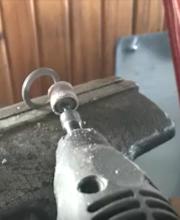
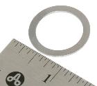 Shims used are from MGB, but the shim ID is too small and must be opened up with a Dremel grinder to fit the larger outboard spindle diameter of the TD or MGA.
SHIM, front hub .003" -- Moss Motors 263-500
SHIM, front hub .005" -- Moss Motors 263-510
SHIM, front hub .010" -- Moss Motors 263-520
SHIM KIT, front hub -- Moss Motors 263-508
Includes 2 each 0.030", 0.010" and 4 each 0.005", 0.003"
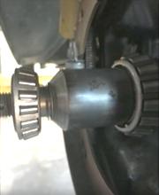
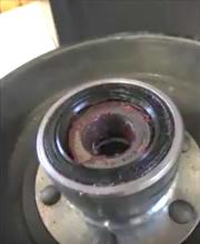
The outer bearing will be Timken 07079-07205
Bore 		= 20.0-mm = 0.7874"
OD 		= 52.0-mm = 2.0472"
Bearing width	= 15.01-mm= 0.5910"
Cone width 	= 14.26-mm= 0.5614"
Cup width 	= 12.7-mm = 0.5000"
The inner bearing will be Timken 30306M
Cone part no:   = X30306M
Cup part no:    = Y30306M
Bore 		= 30.0-mm = 1.1811"
OD 		= 72.0-mm = 2.8346"
Bearing width	= 20.75-mm= 0.8169"
Cone width 	= 19-mm = 0.7480"
Cup width 	= 16-mm = 0.6299"
(Click for larger drawing image).
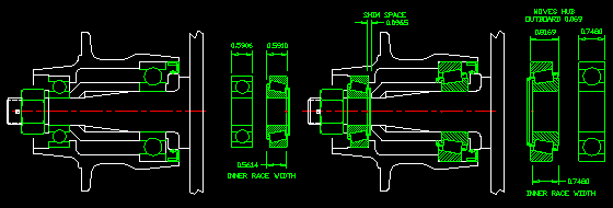
Ball bearings on left, Roller bearings on right
Note that the roller bearings are different width and offset from the original ball bearings, but you have to look at the width between the side thrust faces of the roller bearings, and the length of the inner bearing race relative to the inner race spacer and required shims. The inboard roller bearing inner race width is same as the original ball bearing, so it does not change location of the inner race spacer. However, the inboard roller bearing thrust width is slightly greater than the original ball bearing, so it pushes the rotating hub outboard about 0.069". That in turn relocates the seal slightly outboard, which may come close to messing up the sealing lip interface (see picture).
The outboard roller bearing has a difference between thrust width and width of the inner race that will increase shim space another 0.029". Total space for shims is then nominally 0.098" (give or take a bit depending on fits and tolerances). The standard hex nut drawn in place of the original castellated nut gives an idea of the amount of outboard dislocation of the nut (about 1/10th inch), giving a possibility of interference for the retaining split pin.
I haven't done this yet, but other's have, and I have been assured that it works. I would be happy to hear of anyone else's experience if they do this conversion.
There was a reason why I do these CAD layouts. I wasn't happy with the large stack of shims, so I did more searching, and I found a better bearing for the outboard position. This one has wider inner and outer races, but the same thrust width, about 30% higher load capacity, and it should work with only about 0.020" shim stack.
 (Click for larger drawing image). (Click for larger drawing image).
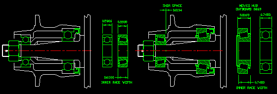
 Ball bearings on left, Roller bearings on right Ball bearings on left, Roller bearings on right
This outer bearing will be Timken 157-153
Bore 		= 20.0-mm = 0.7874"
OD 		= 52.0-mm = 2.0472"
Bearing width	= 15.00-mm= 0.59050"
Cone width 	= 16.20-mm= 0.6380"
Cup width 	= 15.0-mm = 0.5900"
The procedure for adjusting shims in the roller bearing setup is taken from Section K.8 of the MGA Twin Cam Workshop Manual. The same procedure should be noted in the MGB Workshop Manual.
ADJUSTING THE FRONT HUB BEARINGS
 The end float in the hub bearings must be checked and adjusted whenever the hub has been dismantled for attention or when the play in the hub bearings becomes excessive. The end float is adjustable by means of shims situated between the outer bearing an the bearing distance piece. The end float in the hub bearings must be checked and adjusted whenever the hub has been dismantled for attention or when the play in the hub bearings becomes excessive. The end float is adjustable by means of shims situated between the outer bearing an the bearing distance piece.
 Proceed as follows to obtain the correct setting: Proceed as follows to obtain the correct setting:
 (1) Assemble the hub, using no shims, and mount the assembly on the stub axle. Fit the stub axle nut and washer and tighten the nut until the hub bearings bind. This will put the outer rings of the bearings fully against their rotating flanges inside the hub. (1) Assemble the hub, using no shims, and mount the assembly on the stub axle. Fit the stub axle nut and washer and tighten the nut until the hub bearings bind. This will put the outer rings of the bearings fully against their rotating flanges inside the hub.
 (2) Remove the stub axle nut and washer and pull out the center of the outer bearing. Insert a sufficient thickness of shims to produce an excessive amount of end float and note the total thickness of the shims used. Fit the bearing center, stub axle nut, and washer and tighten the nut. (2) Remove the stub axle nut and washer and pull out the center of the outer bearing. Insert a sufficient thickness of shims to produce an excessive amount of end float and note the total thickness of the shims used. Fit the bearing center, stub axle nut, and washer and tighten the nut.
 (3) Measure accurately the total amount of end float in the bearings. Remove the stub axle nut, washer, and outer bearing center. Reduce the number of shims to a thickness which will give and end float between .002 and .004 in. (.051 and .102 mm.). (3) Measure accurately the total amount of end float in the bearings. Remove the stub axle nut, washer, and outer bearing center. Reduce the number of shims to a thickness which will give and end float between .002 and .004 in. (.051 and .102 mm.).
 (4) Replace the stub axle nut and washer and tighten the nut to a torque wrench reading of 40 to 70 lb. ft. (5.33 to 9.68 kg. m.). Latitude for the torque wrench reading is given so that the nut can be tightened sufficiently to align a castellation with the stub axle split pin hole. Insert a new split pin. (4) Replace the stub axle nut and washer and tighten the nut to a torque wrench reading of 40 to 70 lb. ft. (5.33 to 9.68 kg. m.). Latitude for the torque wrench reading is given so that the nut can be tightened sufficiently to align a castellation with the stub axle split pin hole. Insert a new split pin.
|


