The MGA With An Attitude
MGA Twin Cam Ignition Curve - TC-304A
Early Vacuum Distributor
The Twin Cam distributor was change from vacuum advance type to non-vacuum all-mechanical type at engine number 2222 (and included two dozen engines a little earlier in production). The early distributor is BMC part no. 1H811. The later distributor is BMC part no. AEJ41. See CSM MG/296 (147-KB pdf file). For any earlier cars requiring engine service the distributor would be changed at factory expense (no charge to the customer). If we follow the "period" factory instructions, by now all Twin Cams should have the non-vacuum distributor. The later distributor also had much extended mechanical advance curve, which reduced power output some at engine speeds below 6000 rpm. The engines were also subsequently changed to lower compression pistons, lowering power output even more.
At the time of these changes the factory was dealing with a rash of failed engines with holes burned in the pistons. It was discovered later that the problem was a result of fuel frothing in the SU carburetor float chambers at certain resonance vibration frequencies, causing fuel mixture to go excessively lean (never happened with Weber carburetors). Solution to the fuel frothing problem is to install the carburetors on flexible mounts.
With that resolved, there is no apparent reason for changing the distributor, so now some people are interested in returning the distributor to original specification with quicker advance curve and a vacuum unit. Keep in mind the quicker mechanical advance should give better torque (more power) at lower engine speed, but the vacuum advance function is primarily for fuel economy improvement (and possibly cooler running) for normal road speed at partial throttle. Competition cars are commonly either on full throttle or off the throttle for shifting or braking, in which case the vacuum function serves no useful purpose. Many race cars have the vacuum pipe disconnected or the vacuum mechanism otherwise disabled (or removed). So the vacuum unit is of interest primarily for street cruising, not for competition work.
For those who may be interested in the early distributor spec, it is essentially the same distributor as used on the pushrod engines. Since modern fuel formulations are significantly different from what was available when the cars were in production, your engine may benefit from some time spent on a dynamometer to determine current optimal specifications for fuel needles and ignition timing.
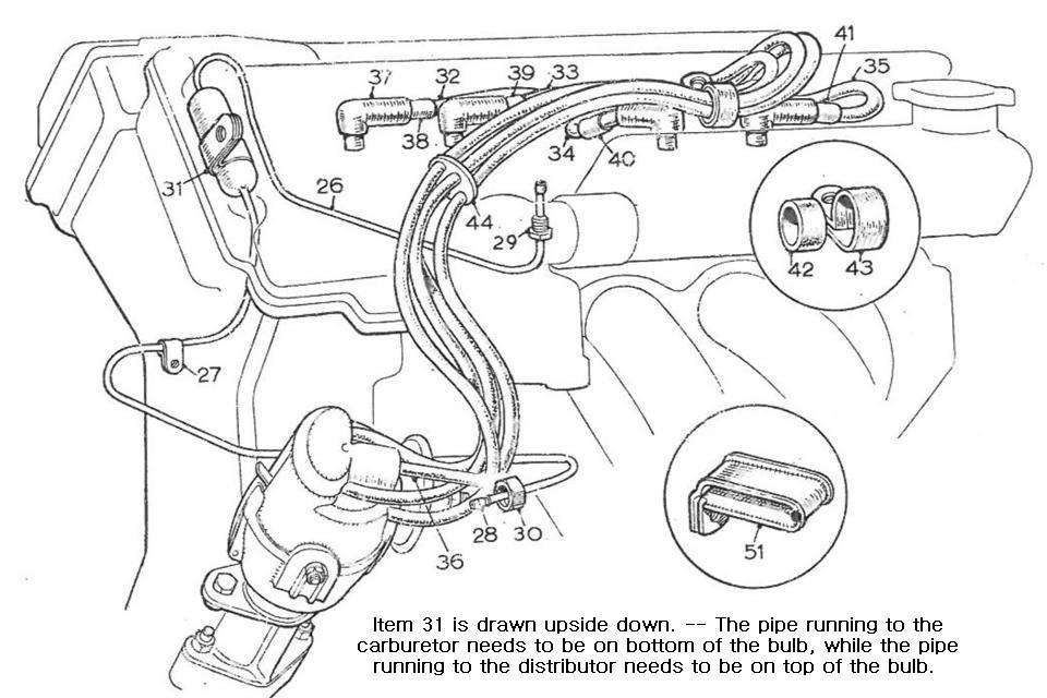
With help from our friend Michael Anderson in Australia, and a picture from Mark Wellard in Australia, we have notice of a drawing error in the Twin Cam Service Parts List. For those interested in fitting the early production vacuum distributor and the connecting vacuum pipe, the illustration shows the pipe running from the distributor across the front of the engine, likely just below the cylinder head, then to the fuel separator bulb on right side just aft of the engine front plate, then connecting to bottom of the front SU carburetor. Problem is, the fuel separator bulb is drawn upside down. The pipe running to the carburetor needs to be on bottom of the bulb, while the pipe running to the distributor needs to be on top of the bulb.
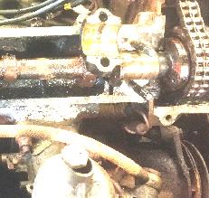
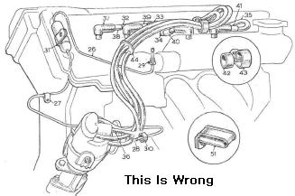
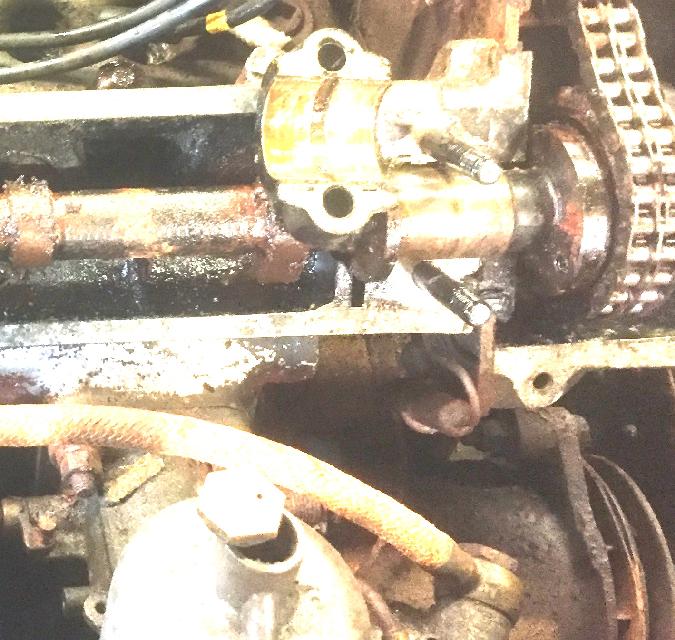
Photo above left shows just a glimpse of the fuel separator bulb on an original installation located on right side of engine aft of the engine front plate, above the generator, just forward of the front carburetor. It is verified by the owner that the bottom pipe goes to the front carburetor. Given the correct vacuum pipe assembly, it should also be obvious from the length of the pipes which one goes to the carburetor.
|