The MGA With An Attitude
CLUTCH Pressure Plate Assembly - MGA Twin Cam - TC-306
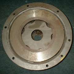
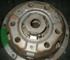
The Twin Cam clutch pressure plate assembly is somewhat different from those in the pushrod engine cars. It has slightly stronger pressure springs and also an intermediate plate called a "spider". In the picture below left you can see the spider plate through the center hole of the heavy pressure plate. In the picture below right there is a small arrow pointing to one of the nuts which secure the spider to the cover.
The eye bolt is essentially stationary relative to the cover, while the pressure plate moves back when you depress the pedal. With the standard clutch the pressure plate is sliding aft/fore on the front spigot of the eye bolt. Pressure plate alignment (and torque) is taken care of with the three large peripheral slots in the cover. The pressure plate in turn aligns and guides the front spigot on the eye bolt. The eye bolt has to carry/resist the radial force applied by centrifugal force on the release lever at high rotational speed (which is substantial).
When you depress the pedal at high engine speed, and the pressure plate slides back on the eye bolt spigot, there must be substantial frictional resistance in the spigot guide hole due to the lateral force on the spigot. This would make the pedal; harder to press at high speed, and would make the pedal rise slower with less feedback force when released. If you carry this to extremes and spin the thing fast enough the lateral force on the spigot could conceivably give enough friction to prevent re-engagement of the clutch.
With the Twin Cam clutch the front end of the eye bolts (spigot end) nests in the diaphragm plate, not in the pressure plate. The diaphragm is attached to the cover and does not move relative to the eye bolts. This effectively eliminates all of the spigot friction which is inherent in the standard MGA clutch, and helps to make pedal force closer to equal on the down and up strokes. This means you can have a stronger clutch with slightly heavier springs and still have reasonable pedal pressure on the down stroke regardless of engine speed. The clutch also does not have that nasty tendency to resist engagement at high speed.
The Twin Cam clutch cover has additional cups around the pressure springs to keep them in place due to the higher RPM operating range. There are also small spacers (4.3-mm or 0.169-in thick) between the housing and the flywheel at each of the mounting bolts. Most are welded to the cover but some are not. The illustration above, taken from the factory Service Parts List shows the spacer as a separate part. Purpose of the spacer is to move the clutch cover slightly rearward to accommodate a thicker friction disc. If these spacers are missing the clutch will not disengage.
The Twin Cam clutch disc is thicker than the standard disc used for the pushrod engines. I presume the factory thought it was a good idea to provide thicker friction material for longer lasting clutch under high performance conditions. This implies that with the increased power and torque of the Twin Cam engine they may have been pushing the 8-inch clutch design to its limits. There is more about this thick clutch disc and spacers in the following article.
|