The MGA With An Attitude
MGA DIPPER SWITCH Assembly and Service - ET-114
At 05:27 PM 12/29/04 -0700, Russell Goebel wrote:
>"A couple of weeks ago the outside cover on the dip switch fell off. It looks as though the cover is joined to the switch by a rivet and held under spring pressure."
It is a small projection of the spindle peened over to retain the cover. With prolonged usage the foot traffic can wear away at the rivet head, and normal angular forces may eventually loosen the rivet.
"Is it possible to re-attach the outside cover of the switch with a small self tapping screw or is the part not repairable?"
You will have to drill and tap for a machine screw. Try to use a truss head screw (very low profile domed head) and a touch of thread adhesive to be sure it stays put. Do a nice job of it and it may be good for another 40 years.
The problem sounded familiar, as I recall having mine apart for cleaning the contacts once, either during or immediately after restoration, around 150,000 miles. I haven't looked at it since. The car now has 343,000 miles, and no signs of trouble with the dipper switch. I suppose the contacts become corroded from a long period of non-use, resulting in high contact resistance, but seem to go on forever trouble free with regular usage.
At 08:08 PM 12/31/04 +1000, Russell James Goebel wrote:
"Completed the disassembly of the dipper switch today, cleaned the contacts, drilled and tapped the spindle and used a round head screw. A little bit of grease around the spring then reinstalled and the unit works fine."
At 06:32 PM 1/9/05 +1000, Russell James Goebel wrote:
".... pictures attached."
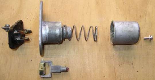
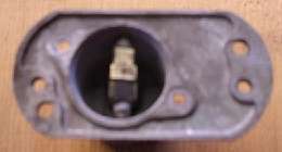
"Once the part is removed from the vehicle drill out rivets (2) holding down the back cover using a 1/8th drill bit. Remove the back cover.
"At this point I was able to remove the spindle as the switch had fallen apart as outlined previously. However if still attached then proceed and remove the spindle by grinding down the rivet holding down the front cover (the cover is under spring tension). Please note the position of spindle on removal, then clean all contacts.
Note: If an ohm meter shows internal resistance less than 1/4 ohm, and the switch operates well otherwise, you do not need to disassemble the back end to reattach the front cover. If you are opening the back to clean the contacts, but the button operates well you would not need to remove the front cover.
"Once the cover has been removed, the remains of the rivet will need to be drilled out using a 1/8th drill bit. The use of a 1/8th drill allows tapping of a 5/32nd thread (#8-32UNC or 4mm). It is probable a 3/16th thread could be tapped (#10-32UNF) - however I went with the 5/32nd. Not having a drill press available managed to get a usable thread length of about 9mm, about 5/16th.
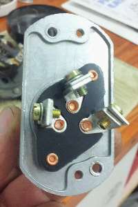
The internal operating mechanism consists of a moving yoke holding a rotating square phenolic spindle wrapped with copper contacts. When the switch is depressed the spindle is caught by a small hook on one of the base contacts causing the spindle to rotate 1/4 turn to change the contacts.
"Reassembly: Using thread lock on the 5/32nd bolt (screw) and some grease (sparingly) around the spring, replace the front cover. Note the original position of the spindle in relation to the body of the switch - it should be across the body of the switch (see picture). It can be replaced in any one of four positions (only two of which will allow the remainder of the assembly).
"Originally the back cover was riveted using two 1/8th countersunk rivets. Due to the position of the rivet(s) it was not possible to use pop rivet gun - so I used two 1/8th bolts (countersunk flat head screws) with Nylok nuts."
Thanks to Russell James Goebel for the photos and notes.
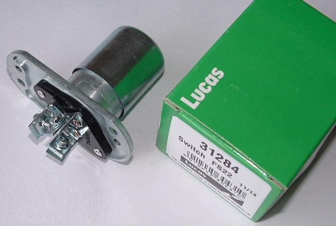
Replacement switch
Photo from Jim Bowlby
|
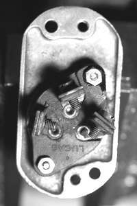
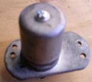
Repaired original switch
Photo from Dennis Davis
|
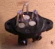
When connecting the wiring you need to know which screw terminal is the input terminal. Use a test light or ohm meter to determine which two terminals are electrically common, and which one is not connected. Click the switch once and check again. The one terminal that is always connected to one of the others is the input terminal and will get the solid blue wire.
Photo at left shows the switch in orientation as installed in the MGA, long end up and "Lucas" name inverted. The center terminal is the common terminal that gets the blue wire. The other two terminals are interchangeable and take the striped wires.
Addendum September 2011:
The internal bits are gross motion electrical contacts. That means the conducting contact parts wipe across each other each time it operates, so the contacts are self cleaning. The usual cure for dirty or corroded contacts is to operate the switch through about 100 cycles to rub the contacts clean. In other words, kick the crap out of it with your size 12 boot. If that doesn't do it you can drill out the rivets in back to see what's happening inside. A healthy switch should have less than 1/4 ohm resistance in the connections, and none of the terminals should ever be shorted to the housing.
August 3, 2017:
In 2013 and again in 2017, the Moss Motors replacement dipper switches have been faulty and hazardous, failing to switch and shorting to ground. This has the potential to distract the driver, blind oncoming drivers, kill all lights, and possibly burn the wiring harness or start a fire. See Faulty Parts report.
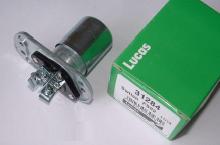
Autoelectrical Spares in the UK are selling genuine new Lucas FS22 switches. I have not had the opportunity to test these parts.
http://www.autoelectricalspares.co.uk
Also search the net for "Lucas FS22 switch" for other sources. Beware of "reproduction" parts.
|