The MGA With An Attitude
FUEL GAUGE FUNCTION -- FG-101c
Begin disassembly by removing the front trim ring and the glass lens. A firm twist should remove the trim ring which has three tabs that engage a small lip on the case. Notice the three notches in the front edge of the case. Just turn the ring until the tabs will pass through the notches and then pull the ring forward. Inside of the ring you should find a rubber gasket which holds the glass lens in place. The lens sits inside of the case and against the forward cupped edge of the black faceplate, and in turn holds the faceplate in place. It would be nice to think that the rubber ring was providing a dust seal for the gauge, but in fact the gauge is not completely sealed and can in time get dusty inside. Having gotten this far it is now obvious how you can open the face to clean the lens and faceplate if you should feel the need. Be aware that you cannot remove the trim ring while the gauge is clamped firmly in the dash panel.
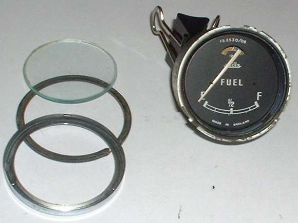
Lens removed.
Also notice a small black tab at the lower left next to the case notch. This is an extension of the black faceplate and is used to key the orientation of the faceplate by fitting into a smaller notch in at the edge of the case. The faceplate is removed by prying it forward (carefully please), mostly at the bottom but also a little at the top, until the bottom of the faceplate just clears the front of the case and the curved slot near the top just begins to clear the elbow of the indicator needle. At this point you slide the faceplate downwards to remove it from the needle, hopefully without bending the needle too much. The needle will most likely bend forwards a bit in the process, but not to worry as it is also very thin and soft material so it can be bent a little several times without risk of a stress crack. When it's time for reassembly you just nudge the needle back into plane after reinstalling the faceplate.
Face removed.
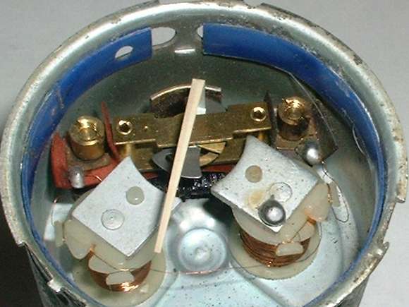
Once the face is gone we get to see the interesting bits inside. The blue ring around the front of the case is a transparent plastic color filter for the external light source. You can see that this ring does not completely cover the slots around the case, which is why the unit is not dust proof. Under certain operating conditions there is up to 3.5 watts of heat being generated inside of this gauge. This heat is adequately dissipated through internal air convection and heat conduction through the metal case (it will be warm to the touch when operating), so if you had a mind to better seal the unit at this location it should not harm the unit to do that.
Just below the horizontal centerline of the case there are two small electro-magnet coils. The steel plate at the front of each coil becomes the field magnet that moves the armature (to which the needle is attached). This plate is attached to a steel stud which extends through the back of the case at the adjusting slots. The one on the left is just a mounting post, but the one on the right also serves as the grounding point for that coil. Notice a small dab of solder on this plate where the hair size wire is attached. Also keep in mind that all of the wire inside of this unit is VERY small, measuring only 0.004 inch in diameter, which is about equal to the thickness of a sheet of printer paper, and barely thicker than a human hair. That's 38 AWG or 42 BSWG. These wires are enameled copper wire, and you wouldn't believe how thin the insulation is. Please exercise due care when handling these wires, as they are quite easy to break but not easy to handle for reattaching. You may notice that both of these coils have a wire soldered to a ring terminal attached to the right side screw post, meaning that the coils are attached to each other. If you remove one coil from the case without taking both together you WILL break a wire. Also notice that the last wire for the coil on the left is soldered to a ring terminal attached to the left side screw post.
A couple more notes about these coils. If you should remove them from the case for any reason, notice that they are left and right handed parts. The crescent shape at the edge of the front plate facing the armature is not symmetrical. The flat edge closer to the center of the gauge is shorter than the flat edge farther from center. This is not particularly obvious from the viewing angle in these pictures. Also remember that these are magnets, so the polarity counts. If you should find the need to rewire any of them, and you happen to reverse either the winding direction or the end terminals, the gauge will not work. If you get the polarity wrong, just switch the wires.
Now to continue disassembly you only need to remove the two slotted nuts from the screw posts and all of the parts shown in the picture below can be lifted out. First remove the slotted nuts, then lift off the ring lugs that connect the coil wires here, and then lift out two bits of insulating paper, the metal armature assembly carrying the indicator needle, two insulating shoulder washers, one piece of heavy insulating card, and then a THIRD electrical coil. This third coil is composed of resistance wire, and is wound around a flat phenol plastic stick. The electrical connections for this coil are made where the wire is wrapped through the large holes at the ends of the stick where they will make contact with the screw posts.
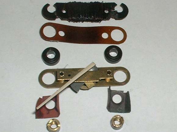
Armature, insulator parts and upper coil removed in order displayed.
Notice that the posts are electrically isolated from the case, because these are the external connection points for the Battery power and Tank signal wires. The small wires are electrically connected to the posts and to the third coil (the resistor), while the armature is electrically isolated.
|