The MGA With An Attitude
FUEL GAUGE CALIBRATION -- FG-102e
So by now you're all impatient and waiting for the bottom line, so here it is, the quick and easy way. You may be able to test the gauge in this manner while it is in the dash, but you most likely won't be able to do any adjustments there, because the mounting bracket will be obstructing access to the adjusting screws. By the time you move the mounting bracket you might just as well pop the gauge out of the dash for easier access to the back.
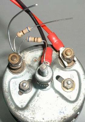
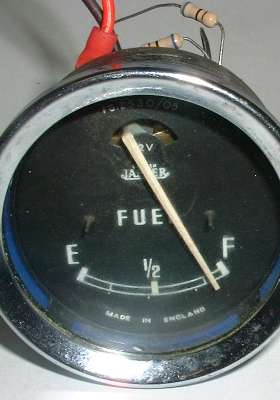
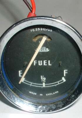
You will need two wires only connected to the gauge, just the power ("B" for Battery) and ground wire (case connection), so you can do this anywhere you have a 12 volt supply. Disconnect the signal wire from the "T" terminal and position it out of the way. Then connect two 68 ohm resistors and one short jumper wire to the signal terminal (marked "T" for Tank) similar to the first picture here. Also connect one of the resistors to ground on the case, and you can leave it connected that way for the duration of this calibration exercise. That first resistor at 68 ohms represents the maximum resistance that should be in the sender circuit with a full tank of fuel. All other signal resistances will be lower. With the power on and one resistor connected the gauge should read near the full mark. NOTE: Keep the gauge in an upright position whenever you are looking at the face reading.
When you touch the second resistor to ground on the case, as in the next picture below, the two resistors in parallel will halve the signal resistance to 34 ohms, which should leave the gauge reading somewhere near the 1/2 full mark.
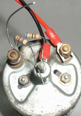 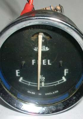
When you touch the jumper wire to ground on the case, as in the next picture below, you are reducing the signal resistance to zero, which should have the gauge reading very near the empty mark. These are the only electrical connections you will need to do the gauge calibration.
One resistor = Full. Two resistors = Half. Grounded jumper = Empty.
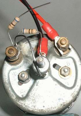 
The magnet behind the "F" controls pull to the right. The magnet behind the "E" controls pull to the left, but this controls the center position of the needle (linearity adjustment) more so than when the needle is near the "E". I will call these the "F" and "E" magnets respectively. To adjust the magnets, loosen the clamping nut bridging the slot at the back, move the stud slightly along the direction of the slot, and tighten the nut. Moving the magnets upward and inward towards the rotating armature increases the pull of the magnet (and vise versa). Keep in mind that the "F" magnet grounds on the case through the mounting post, and the needle will be jumping around while you are moving the stud, so you need to tighten that nut to get a solid reading on the gauge.
If the "F" magnet is too close to the armature it can cause the needle to suddenly move away from the "F" mark, never to return again until you back it off a bit. If the "E" magnet is moved too close to the armature it will overcome the pull of the "F" magnet, and the "F" magnet cannot be adjusted to get the needle to move all the way to the "F" mark. If you cannot get the needle to move to the "F" mark, try backing off both of the magnets away from the armature to the bottom of the slots and start again.
NOTICE and CAUTION:
When you loosen one of the calibration nuts, keep in mind that there is a very shallow step (key) on the magnet mount that rides in the slot to keep the magnet aligned toward the armature. If you loosen the nut more than one turn the key can jump out of the slot, allowing the magnet to rotate. This not only screws up calibration of the instrument but may also break the hair size wires connecting the coil inside. If you break one of the internal wires you get to open the instrument to re-attach the tiny wire (which is not particularly easy to do).
The procedure for final calibration is as follows:
a.) With one resistor grounded, move the "F" magnet upwards until the needle moves near the "F" mark and secure it in place.
b.) Ground the jumper and move the "E" magnet slightly upwards until the needle moves to the general vicinity of the "E" mark, and secure that magnet.
c.) Unground the jumper and check the reading at the"F" mark again. If necessary repeat the adjustment of the "F" magnet to put the needle back on the "F" mark.
d.) When you get the needle to swing between "F" and "E" by alternately grounding the jumper, then ground the second resistor and observe the position of the needle, hopefully somewhere in the general vicinity of the 1/2 mark. You can then use the "E" magnet to adjust the position of the needle to fall on the 1/2 mark. This is the linearity adjustment. This may affect the "F" reading some, but should not affect the "E" reading much to notice.
e.) You can then fine tune the "F" reading again, perhaps followed up by fine adjustment of the "1/2" reading. One or two more iterations of this should get the gauge reading spot on for Full, Half, and Empty. When you get to that point you are finished, as there are no more adjustments available for this gauge.
Secure the adjusting screws, check the calibration one last time, remove the resistors and the jumper wire, and return the instrument to its proper mounting in the car. Be sure the gauge is getting full system voltage from the power wire, and be sure that the gauge is grounded to the chassis and/or to the ground wire in the harness. If the gauge does not read properly in the car after calibration, then the fault will lie in the signal circuit. Check the wire running from the gauge to the tank sender unit, and check for proper grounding of the fuel tank to the frame of the car, and finally (if you must) check the resistance range of the sender unit in the tank. If the gauge is calibrated and works properly on the bench, then when installed in the car it needs only power, ground, and the correct resistance signal from the tank sender unit, which should run from 70 ohms to zero resistance as the fuel level goes from full to empty.
Now if I explained all this properly I should get no response at all to this next comment. I may live to regret this, but if you're still having trouble with your fuel gauge after doing all of this, feel free to drop me a note.
Best Regards,
Barney Gaylord
1958 MGA with an attitude (and a 46 year old working fuel gauge)
|