The MGA With An Attitude
|
| MGAguru.com |
|
MGAguru.com |
MGA Seat Belts - Shoulder Harness Bracket Retrofit #3 -- INT-120A3
 On 27 December 2017, David K Brenchley in Kent, UK wrote:
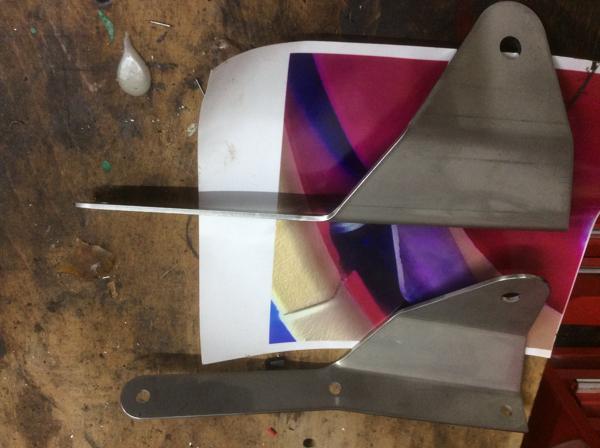
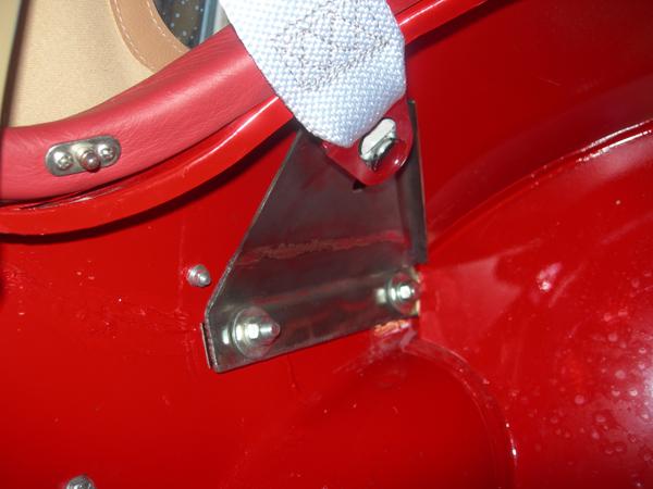
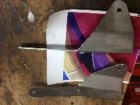
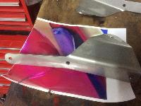
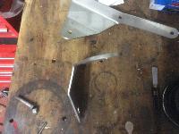
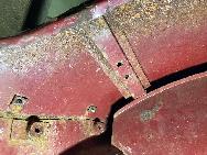
 "I have a pair of laser cut stainless seat belt mounts as per the photos. They came with my MGA from John Bray so maybe he knows where they came from? The three holes on the longer side fit the bolts that hold the rear wing on, one of which is in the boot, these bolts will need to be replaced with longer ones. The hole on top is for an eye bolt to clip the seat belt to. Very well made with no sharp edges.
 On 29 December 2017, John Francis in Oxfordshire, UK wrote:
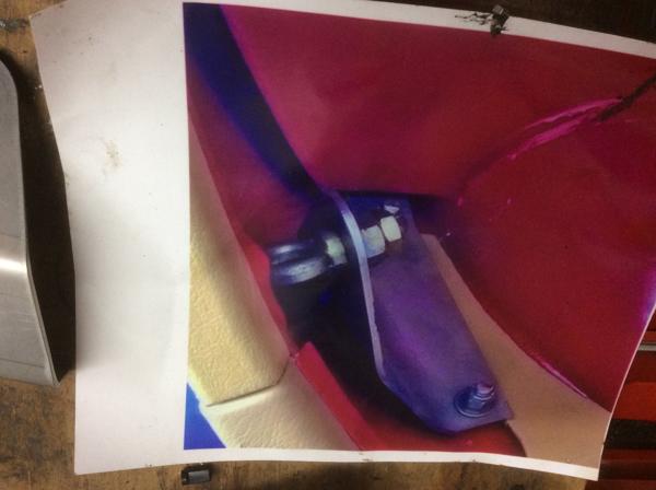
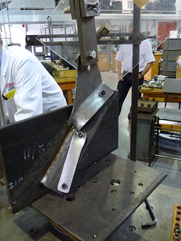
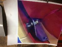
"I developed some brackets some years ago. They were tested to failure in a University laboratory, and I have them fitted to my car. Here is a photo of the 3mm bracket design version tested to failure, and a photo of it installed in my car".
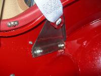
"Here are the drawings and test results for the seat belt mountings that I developed. Although I did get the design tested at Oxford Brookes University to see what the maximum load it would take and how it would fail, I can in no way guarantee that the design is suitable for seat belt mountings. Anyone using the design must satisfy themselves that it is OK to use. I designed it for my own use only and cannot guarantee its fitness for purpose for anyone else". I made my brackets out of two pieces of steel and then welded them together". -- John
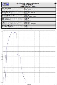
2mm -- 19.44 kN = 4370 Lb
|
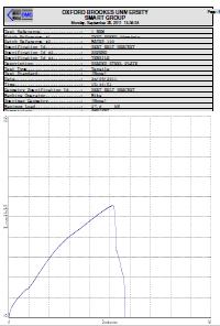
3mm -- 27.8 kN = 6250 Lb
|
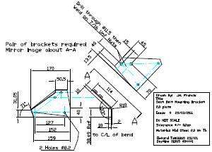
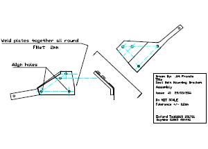
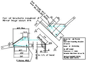
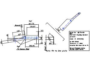
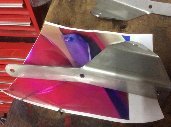
There are a couple small errors on the drawings (not updated after it was finished). The larger sheet is 2.0-mm thick, and the smaller sheet is 1.5-mm thick, ending up with 3.5-mm total thickness. The three mounting bolts do not lie in the same plane, so some bending of the tail is required for fitting. Having the part in two thinner sheets made it easier to bend to final shape before it was welded together. The test plate used a bolt through the hole (where it broke during testing to destruction). The final design has welded nuts on the back of the plate which will be stronger than just the hole, as the welded nut will spread the load more.
|