The MGA With An Attitude
Body Sill Replacement - RT-615
Box Panel Gussets and Welding
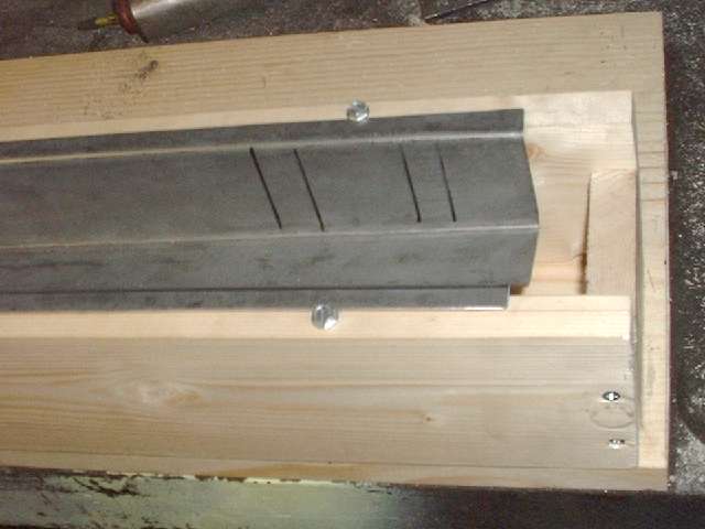
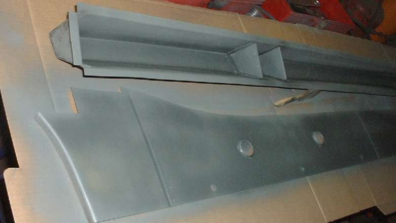
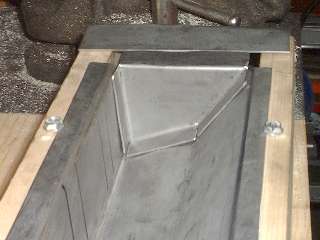
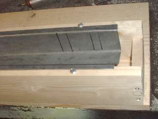 This session starts with a simple box fixture consisting of a pair of 1x4 boards on edge with 3-1/2-inch wide spacers at the ends. With the few flange head screws on top this gently holds the sill box panel with inner face up in a flat plane while I work on fitting the end plates and inner gussets. The black lines inside the top surface of the sill box mark the location for the gussets that will be installed directly in line with the bottom flanges on the door posts.
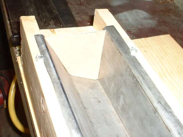
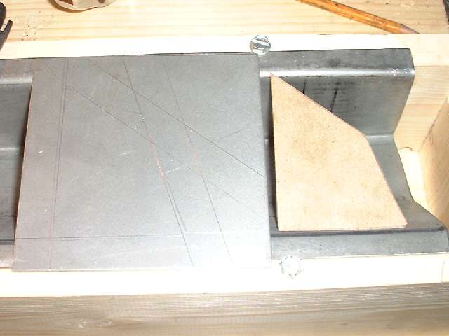
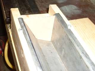
Picture below left shows a cardboard template cut to fit inside the box panel at the large end (front). It is thin cardboard from the back of a pad of writing paper, just hold it over the end of the panel, trace around the inside with a pencil, and cut it out with scissors. Picture below right shows the template with a sheet metal blank. I lay the template on the sheet and run a scribe around it to mark the panel size on the metal, then use a straight edge and scribe to mark the offset of the outer flange width all around. I cut out the blank using the hand held sheet metal shear, then notch the corners using the 3-inch cut-off grinder, and flatten and deburr the blank before bending.
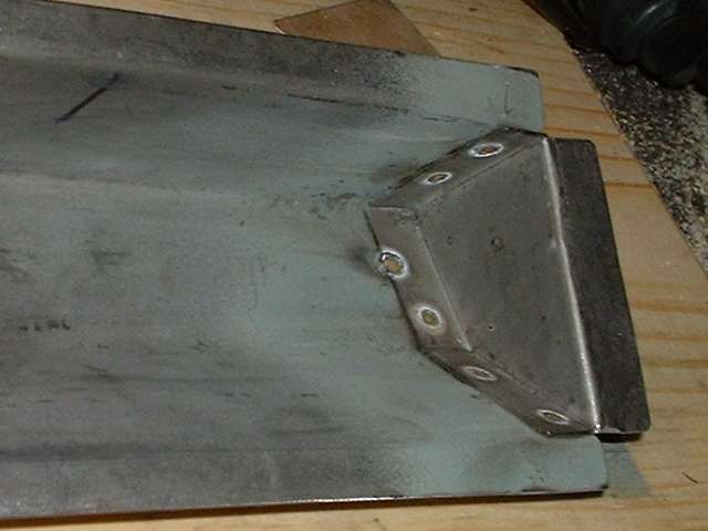
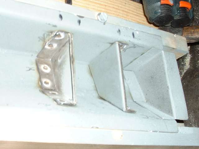
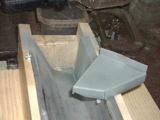
Photos below show the finished end plate. On the first part I guessed at the bend radius and made the bends a little inboard from the nominal bend line. I hammer formed the short center flange first in a vice, then bent the two adjacent longer flanges using the small bending brake. That was followed by some fiddling with hammer to "fine tune" the position of the flanges for a better fit inside the box. For the last flange being bent in the opposite direction, I clamped the part in a vice using a thick spacer on the side that was already flanged, then hammer formed the last flange (in about 30 seconds). Notice the final outboard flange is intentionally out of plane by one thickness of sheet metal. This is where it sits on top of another overlapping body flange at the front of the sill.

I learned a few things making the first end plate, like the little bending brake is a bit of a fiddle for set up, is not terribly accurate for position, and doesn't make a perfectly tight bend. For these short flanges the bench vice and a hammer is both quicker and more accurate for the final shape, being able to make a near zero radius bend, so I don't have to guess at the bend radius.
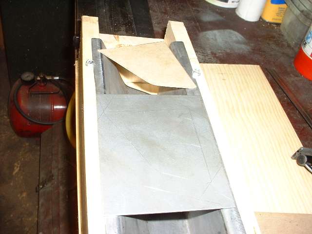
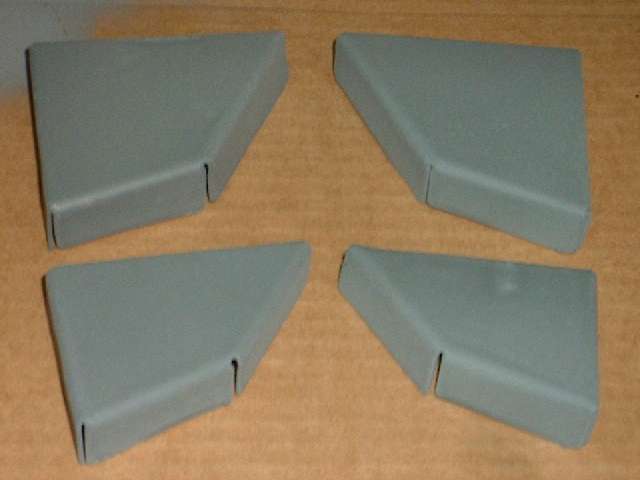
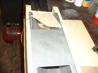
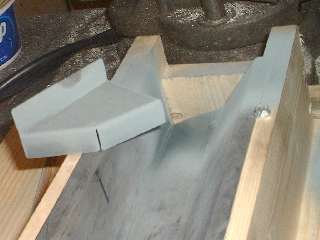
Picture below left shows the cardboard template and blank layout for the smaller end plate. My technique improved considerably this time. I scribed around the template to mark the outer limit of the final part. I then stood a piece of sheet metal on edge just inboard of the scribe line, and scribed along the other side of the sheet to mark an offset for the thickness of the sheet. This is the location for the inside of the intended zero radius bend. This was followed by marking the offset for the width of the flange all the way around. If you look carefully (click for larger picture) you can see the double scribe lines defining the thickness of the sheet at the bend locations.

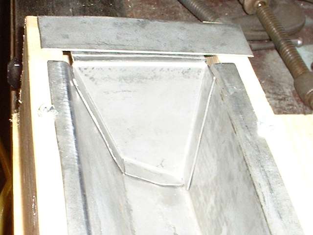
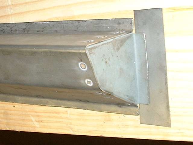
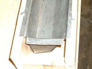
Picture above right shows the finished end plate. All of these bends were done in the vice with a hammer. I used a pair of short angle iron pieces to extend the vice jaws a bit to one side enabling me to make all three of the inward bends with no other spacer blocks. Technique here is to line up the innermost scribe line with the corner of the vice jaw (or angle iron in this case), clamp it tight, then hammer the flange over and down tight against the iron to make the zero radius bend. After three fairly quick bends the part dropped right into place with a good fit and little or no adjustment required. Holding the part in place, I then used a straightedge across the top of the wood fixture to scribe a line on the opposite side of the plate for location of the last bend. This bend will be exactly at the top of the wood fixture. After hammer forming the tight corner, notice the last flange lies in the same plane as box flanges. This is where it will weld onto the rear inner fender (mating to my new inner sill plate of course). (13 Feb 08 pm)
Now I'm on a roll and a little anxious to spot weld the end plates in place, so there is a short pause to wipe the parts down with acetone, quickly blow dry, and spray a little of that nice zinc-rich weld-through primer on the weld zones. Processing the pictures to the web page allows time for the paint to dry before welding.
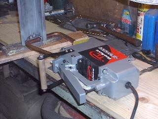 Okay, here's the drill for warp-free spot welding. The general idea is that the only physical force on the work piece or the spot welder tongs should be the pinch force, and no gravity load or twist or out of plane push. Keep in mind it requires at least one hand to squeeze and trigger the spot welder, and it weights 35 pounds. That leaves me with only one hand to hold anything else. So I lay the spot welder on its side on the workbench, and set the work piece on some wood blocks to fixture it in position within the tongs of the welder. There is also a sheet metal shim under the front end of the welder body for fine adjustment of the height at the business end. The sides of the copper tongs should not touch anything metal, as it could cause a short circuit of the high current with "surprising" results (to put it mildly). Only the conical tips of the tongs should touch the work zone. Here my left hand can hold and align the work piece while my right hand can squeeze the big lever and press the trigger on the welder. What you don't see in the picture is a couple of welding clamps that were holding the sheet metal bits together during the first few welds.
|