The MGA With An Attitude
Body Sill Replacement - RT-617
Anatomy of a B-Post Repair
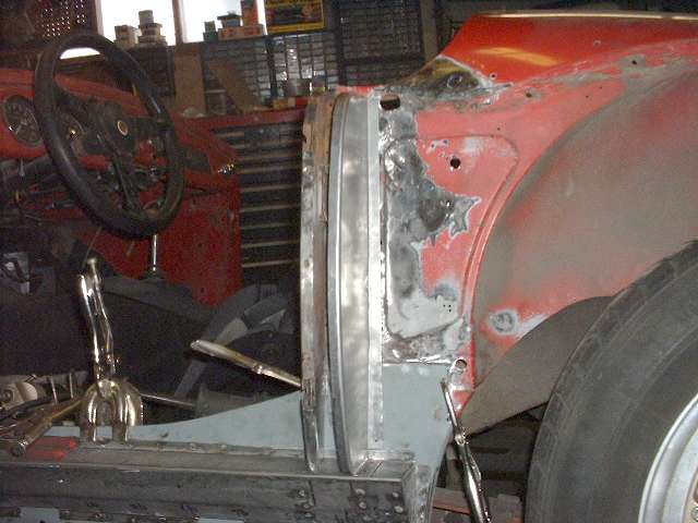
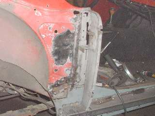
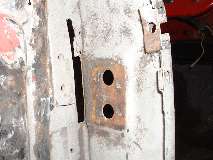
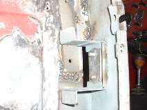
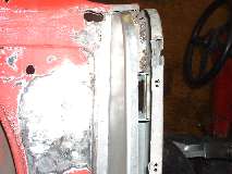
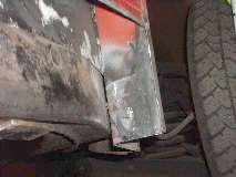
Let's start this with pictures of a repaired B-post on the left side. Above left is the complete new back panel is just sitting there unattached. I will not weld and close the post box it until after the sill assembly is welded in place. The second picture shows the bottom of the back panel with a few punched holes in the flanges. These will ultimately be plug welded with the MIG welder in locations that are inaccessible for a spot welder with the body still sitting on the frame. I do have extended tongs for the spot welder that will reach around the post to weld the back flange. There will be four more plug weld holes (not shown yet) high on the back plate for welding the internal bracing for the striker plate mounting (more on that later).


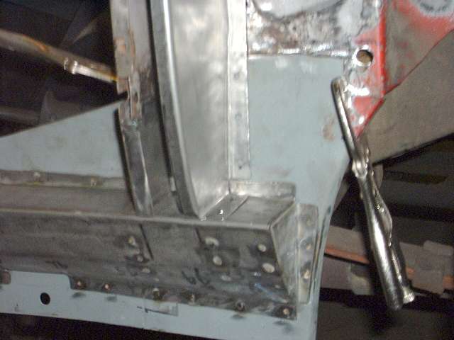
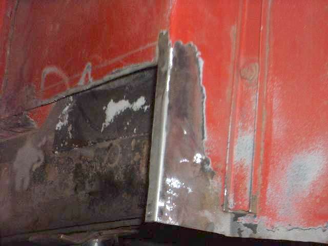
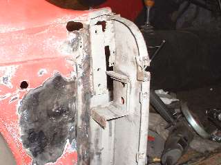
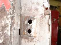
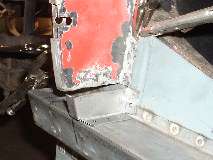
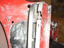
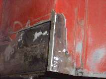
Here is a repair piece welded at the bottom of the front plate. To remove enough of the rusty panel to have solid metal for welding, the horizontal cut (and weld) is about 1/4 of the way up the door buffer bracket. There is a step down near the outboard edge to go below the bracket in order to save the original bracket. I surprised myself here with a good weld on the first try. It was welded from the front side and has good full penetration. It only needed a little sanding on the back side to smooth it out flush, and that could have been left as welded. The front of the weld was ground flat and sanded smooth, as the shut face plate will sit against this surface. Again notice the punched holes for a few plug welds to be made later, as the sill assembly is still not welded to the body. Also notice a small offset at the bottom of the inboard flange to go over the top flange of the box panel. This front panel repair piece was hammer formed using the same wood block that was used to make the back panel.
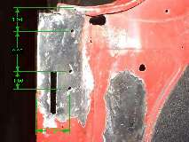
 At left is the bracing bracket behind the striker plate mount. It still needs a touch of sand blasting to clean off the surface rust, but otherwise was judged to be solid enough to keep. The rusted rear panel was removed by sawing away the gussets, then sawing down the inboard edge near the weld flange, then carefully grinding through the back panel to break the spot welds on this bracket. The inboard flange from the back panel and was removed from the inner body using an angle grinder. Same for removing the remaining spot welded flange of the gussets.
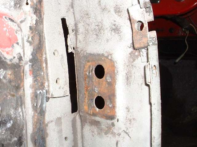
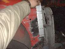
Here is a look inside the right side B-post after removing the rear plate and gussets. There are a few more problems here. The striker mount brace was rusty and broke the top leg with barely a touch. Notice the heavy plate for mounting the folding top frame that I installed 10 years earlier is in good condition, but some sheet metal around it has gone away (poor welding last time). Also there was some thick layered rust hiding between the body inner panel and the body mounting bracket low on the side ahead of the wheel well. Lets fix the striker brace first.
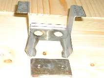
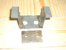
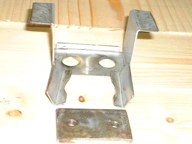
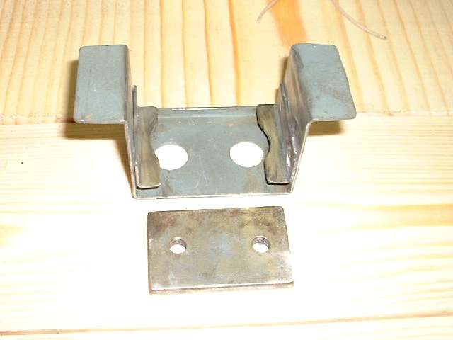
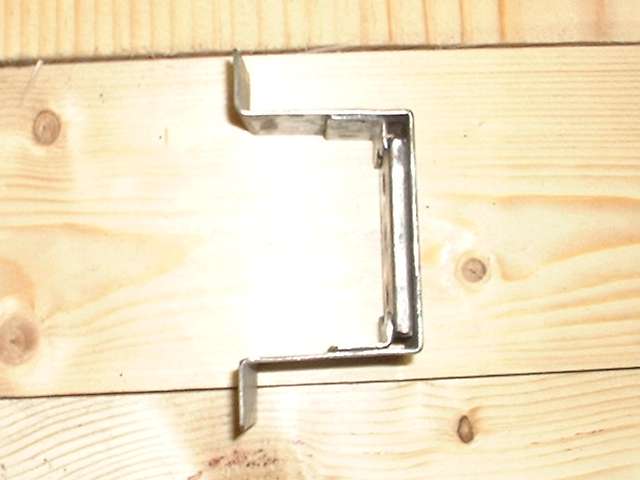
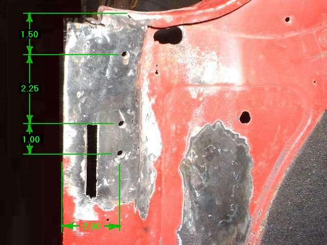
This piece was kind of fun. Considering how thin the original metal had become, it figured to be just as easy to replace the whole bracket rather than to try welding on a leg in tight quarters. Notice the narrow flange along one edge. This is a back stop to prevent the tapping plate from passing all the way through and falling inside the post. Also remember that there is a 4 degree angle on the post front plate. The part starts as a long rectangular strip with the edge notched out in two corners. I bent the narrow flange first (the tough one) by hammer forming over angle iron in a vice (about one minute after it's set up). Then I bent the end tabs in the 18-inch bending brake (don't forget the 4 degree angle before the 90 degree bend). Then I bent the legs up from the flat also with the bending brake. The two 1/2-inch holes were hand drill last (for best placement) while holding the part in the bench vice.
The two internal tabs were easier yet, just clip a small metal blank and bend it with the bending brake. Having made the bracket to original dimensions, I thought I'd give the tapping plate a little more vertical adjustment range. For this I ground the ends of the tapping plate a little shorter, then added the notch in the L-tabs. After deburring, the parts were cleaned in solvent, blown dry, sprayed with the zinc primer, and allowed to dry for half an hour before spot welding. I slipped a thin piece of card stock behind the tapping plate as a temporary shim to provide sliding clearance while aligning and clamping and spot welding the internal tabs.

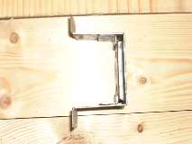
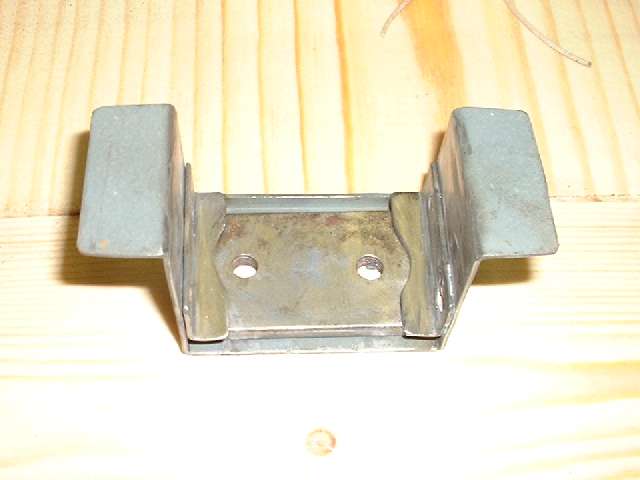
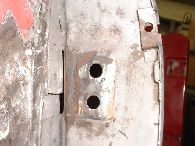
So there's the finished brace/bracket for the striker mount, a lot easier to make than it might first appear. I removed the old one by grinding through the bracket to break the spot welds without damaging the front plate, then sanded off the rust.
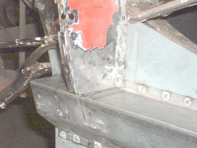
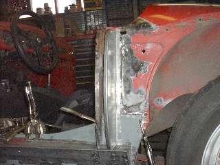
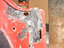 Before welding the new bracket in place it was time to repair that ugly bit of metal around the top frame mounting plate. Getting easier by now, cut away the rusty bits, snip and trim a new piece of metal to fit, weld it in place and grind it smooth. This felt good to clean up a couple of sore spots that I left in haste ten years earlier. Picture on left shows the finished repair, and also a patch in the panel ahead of the wheel arch. Picture on right shows only a minor touch up to the prior welding with some grinding to smooth things out nicer, and a patch just below the cockpit rail a few inches farther back (see another picture of that patch at bottom of page).
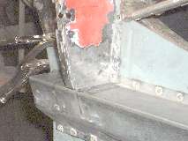
Fast forward a bit for some more zinc primer to dry, then spot welding the bracket in place. All of this stuff will get some Chassis Saver paint (similar to POR-15) before the back panel is installed. Center picture shows another new patch piece for the bottom of the front plate, just over and inch tall this time. It didn't need to be that tall, but it is easier welding and grinding when the weld is not too close to an inside corner. Picture on right shows the finished weld after grinding in front and sanding a little in back. Notice this is still not welded to the sill assembly.
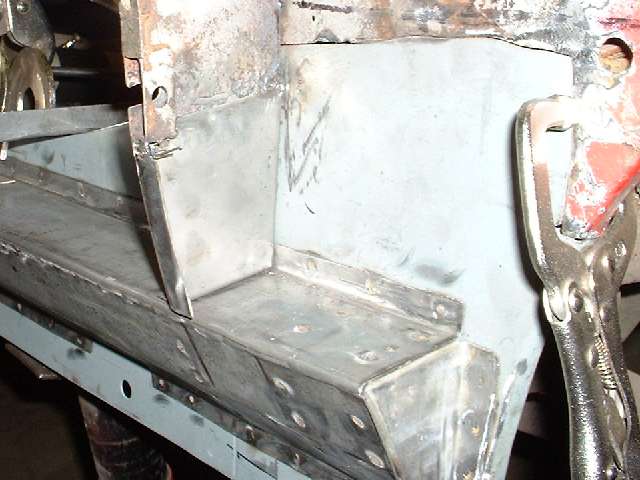
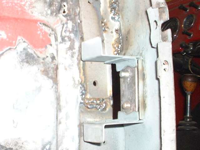
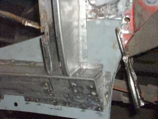
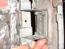
Here is the new back plate set in place after some minor adjustment of the flanges. There will be a few holes punched around the lower flanges for plug welding later. Also see pictures showing the new striker bracket inside the post. That will also be plug welded to the back plate later.

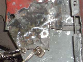
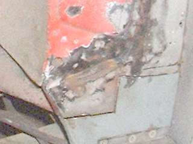
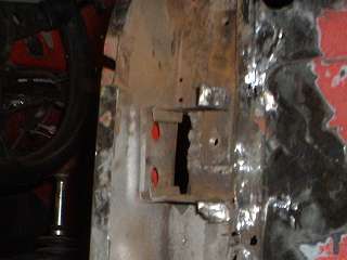
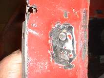
Here's an interesting patch in the old inner panel where it is welded to the body to frame mounting bracket. What looked like a blister in the paint turned out to be a hole in the sheet metal. There was a small area of heavy rust hidden between the sheet metal and the heavy bracket behind. By the time I finished grinding away rust behind there was a cigar shape slot in the sheet metal with an additional hanging tail near the left end. It was otherwise still solidly attached. The easy solution was to cut a patch piece to exactly fit the hole and lay flush, then weld it in. I also punched two holes in the new strip for plug welding. After the patch was welded all around and ground smooth I used a ball peen hammer to push the patch back firmly against the underlying bracket, then plug welded it and ground it again. The slightly depressed plug welds look like a pair of eyes staring out of the darkness.
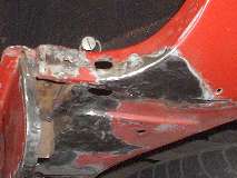
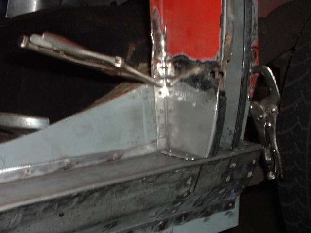
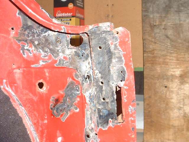
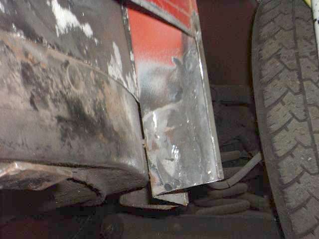
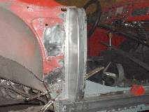
Here are a few pictures of other miscellaneous repairs made a little earlier. The first is a patch on the top body cowling near the B-post. I think this originated just above the fender piping. It originally looked like a blister in the paint, but sanding through the paint revealed a thumb size hole that got bigger by the time all the rust was removed. The other pictures show a patch piece in the body flange at the front of the right side sill. This was one of my first ventures into MIG welding for a real cause, a simple weld in a non-obtrusive location, but it tuned out quite well (after some serious grinding and sanding). The vertical patch piece is less than an inch wide on the front panel. (28 Feb 08)
|