The MGA With An Attitude
FUEL GAUGE FUNCTION -- FG-101e
Here we have views of the gauge without the armature assembly. In the first picture I have reinstalled the third coil, while in the second picture the third coil has been removed. Notice that there is a steel tab riveted to the back of the case near the top and having a curved forward extension. This curved metal tab serves as the opposite magnetic pole for both of the round coils. The flat coil is not intended to be an electromagnet. It is essentially a wire wound power resistor serving as a shunt to reduce current in the left side coil, and relatively increase current in the right side coil (when it carries current). See circuit diagram below.
Also notice the ring terminal wire connectors resting on top of the posts and coils. When one ring terminal is moved from its resting place it falls back into the case because the small wire is not strong enough to support the "heavy" terminal. You will need tweezers or small needle nose pliers to handle these terminals, and do try not to flex the wires too much to avoid stress breaks in the wires.
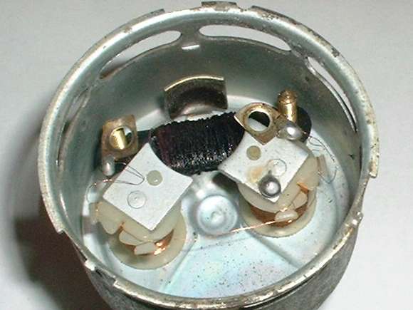
Case with three coils in place.
The field magnets work in concert. The top and the left magnetic poles pull the armature clockwise, moving the needle to the left toward the "E". The top and the right magnetic poles pull the armature anticlockwise, moving the needle to the right toward the "F". In effect the left and right magnets are sharing the top magnet tab. For the sake of simplicity you can just think that the left magnet pulls the needle to the left, and the right magnet pulls it to the right. During calibration, moving one of the magnets closer to the armature increases the attraction and pulls the needle more in the direction of that magnet. More about calibration in the next lesson.
Side note: It has been brought to my attention that some later production instruments may omit the top magnetic tab, and the instrument apparently can work as well without it. Also the third coil may be replaced with a 2 watt power resistor, and the function of the instrument will not be affected.
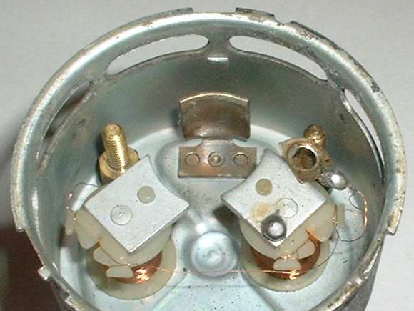
Upper coil removed.
One more note about the construction of the coils. For the purpose of checking the condition of the coils you can measure the resistance. For this gauge the top coil measures 154 ohms, the left coil measures 101 ohms, and the right coil measures 99 ohms. For different units these values may vary by a couple of ohms, but still should be fairly close to these numbers. For complete understanding of the gauge operation you should also know that the sender unit in the fuel tank has a resistance that varies from 0 ohms with an empty tank to 70 ohms with a full tank. For practical reasons (again simplicity) we will generally assume that change in the sender unit resistance is linear with changes in fuel level. In the end you may discover that any non-linearity there may not matter much, as the calibration procedure can tune out most of the non-linearity.
You can do a reasonable job of measuring these resistance values without even opening the gauge case. The right side coil is connected from the right terminal post "T" to case ground, and the resistance there should measure about 99 ohms. Both the left side coil and the upper coil are connected from the right side terminal post "T" to the left side terminal post "B". The combined resistance of these two coils connected in parallel is 61 ohms, so if you get a reading close to that value you may assume that both of those coils are okay. If one of these coils is open circuit the resultant reading would be either 154 ohms or 101 ohms, which would tell you which coil is still good. The only way to measure resistance of these two coils individually is to open the front of the case, remove the faceplate, and disconnect one of the ring terminals from a terminal post. If you are measuring these resistance values with the gauge still mounted in the vehicle you should disconnect all wires attached to the terminal posts to avoid interference from other devices in the vehicle (but you can leave ground wires attached).
Fuel Gauge Circuit Schematic
In Schematic form it is obvious that the variable resistance tank sender unit is wired in parallel with the right gauge coil. When the tank is empty at zero resistance it's clear that the right side coil is shorted out and will carry no current, so the left side coil pulls the needle into direct alignment with the "E" mark on the gauge. As the tank sender unit resistance increases it forces some current to flow through the right side gauge coil which pulls the needle to the right. At the same time the total circuit resistance is increasing, so the total circuit current is dropping, and the left side gauge coil is losing some of its strength. When the tank is full and the sender unit is at maximum resistance the gauge needle should be pointing directly at the full mark. Moving the magnets to different distances from the gauge armature changes their pull, so there is a means to calibrate the instrument, which is the subject of the next lesson.
One other nice feature of this type gauge is that all of the currents in various parts of the circuit are relative to each other, meaning all fixed ratios for any given resistance of the sender unit. This results in the gauge being very stable over a wide range of input voltage, so fluctuations in vehicle system voltage have very little effect on the reading of the fuel gauge, such as a frolicking voltage regulator or operation of the turn signal or brake lights.
Another thing that happens is instant reaction of the gauge needle to changes in sender unit resistance, so that when the fuel in the tank sloshes the gauge wavers accordingly. This gauge behavior may take some getting used to, but at least it makes it easy to tell when you're about to run out of fuel. When the fuel level gets down to the last quart the sloshing is insufficient to raise the sender unit float from the bottom of the tank, so the gauge stops dancing, and you know it's time to gas up or prepare to walk.
|