The MGA With An Attitude
REBUILDING THE MG GEARBOX - GT-203D
GT-203A - Test Drive Inspection
GT-203B - Open Inspection
GT-203C - Disassembly, External
GT-203D - Disassembly , Internal - (you are here)
GT-203E - Disassembly, Gear Clusters
GT-203F - Disassembly, Gears and Synchronizers
GT-203G - Reassembly
Disassembly , Internal
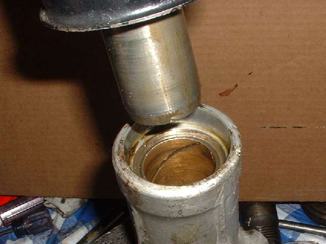
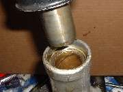 Now referring to the MGA 1500 gearbox. This gearbox has a sliding spline joint where the propeller shaft mates to the rear of the gearbox. Inside here is a bi-metal bearing like a big copy of a kingpin bushing, bronze inside of a steel liner. To check this one you shove the drive shaft front yoke in to the normal working distance and try to wiggle it. When new the working clearance is just 0.002 inch like a crankshaft bearing, no perceptible clearance with oil in it. If the yoke can wiggle more than a few thousandths of an inch, it's a problem. It probably won't self-destruct immediately in normal use, but it can cause a vibration in the drive shaft at speeds over 30 MPH. But what's also nasty is that it beats up the rear seal in short order and the oil leaks out. In one case when mine got especially loose, a new rear seal was completely shot in two weeks. Adding oil daily will save the gearbox but leaves a big oil puddle where you park. Enough about the problem. For the repair check out Replacing the tail bushing.
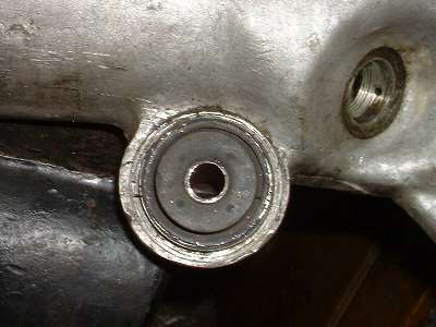
You may want to check or change the rear rubber mount. These are only moderately expensive, but good piece of mind to have a new one in there. The MGA gearbox rear mount is a real pain to change, being a press fit steel shell in a thin aluminum housing.
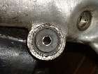 Be careful here, as the aluminum monkey ear on the rear housing is easy to break, especially on the 1500 gearbox. Some reinforcing ribs were added to later models to improve the strength of the case around the rear mount casting. You surely can remove and replace the rear mount without a press if you are willing. Check Replacing the rear mount for details.
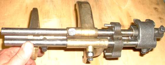
Shift rods with forks, detent block, and selectors
Inside the box, crack loose the jam nuts and remove three pointed nose screws which secure the bronze shift forks to the shifting rods. Take these screws all the way out. The three shift rods pass through a flat steel block at the back of the main case. This block contains detent balls and springs. It is best to remove this as a complete assembly to avoid disturbing these detent parts. Remove two bolts (a thin wall or 1/4 inch drive socket works here) and pry the detent block away from the main housing. This has to be removed from (or with) two steel dowel pins. Extract the entire assembly (the block and three shift rods) from the back, leaving the shifting forks inside. The forks can then be lifted out individually.
Check the working surfaces of the brass shifting forks where they mate with the grooves in the sliding steel hubs. When new these fit almost like crankshaft bearings, just a couple thousandths inch of clearance. After 100,000 miles they get a little loose and wobbly but will usually still work just fine. Don't worry too much unless they're really sloppy. When my original gearbox had about 150,000 miles on it, the forks were working OK. I swapped them out for some younger ones more recently, but only because I had some extra ones laying around and put in the best I had.
Early gearboxes have an extended tube tail on the 3-4 shift fork, all one piece. Later units make the 3-4 fork smaller, and the extended tube spacer on the 3-4 shift rod is a separate piece. The drawings will be different in different places. The Workshop Manual shows the 3-4 fork and tube spacer all one piece like early units. The Moss Motors catalog shows the 3-4 fork and the tube spacer as separate pieces with separate part numbers like the later units. The Service Parts List shows the tube spacer commencing at (G) A290.
 If this is the first time you have opened this gearbox, and you do not know the history of the unit, this is a good time to disassemble the shift rods from the detent block to inspect the detent parts. When you extract the shift rod hold your hand and/or a shop rag over the hole in the detent block to catch the steel ball and spring that will pop out of the hole (or have some spares handy in case you lose these small jumpy parts). When inspecting these parts refer to the following documents:
GT-202 - Why it Pops Out of 3rd Gear
MG-241 - Jumping Out Of Gear (csm)
FT-038 - Incorrect Spring for Shift Detents
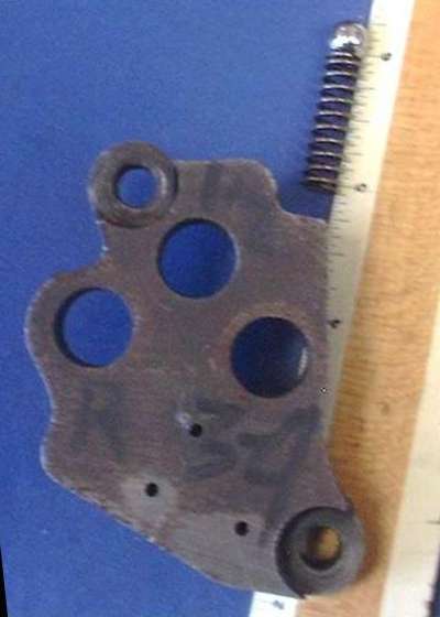
Interest here is to measure depth of the hole for the 3-4 gear detent, and length of all of the springs. If you find the hole to be too deep it can be shimmed. If you find the springs to be too short they can be replaced with correct longer springs, or the short springs can be shimmed to equal the free length of the correct springs. These springs are related to the occasional problem of popping out of 2nd or 3rd gear.
Reassembly is easy enough when you know how the bits work. Put any shims in the hole first, then the detent spring followed by the ball. Press the ball down with a flat tip punch to be flush inside the bore, and then insert the shift rod into the bore to cover the ball detent as you remove the punch.
NOTE: The late model MGB (4-synchro) gearbox has a different arrangement of ball detents at the front end of the shift rods. There you will install the shift rods first, then drop a detent plunger into the hole followed by a spring and a bolt. During disassembly you should remove the detent parts before withdrawing the shift rods.
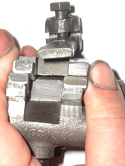
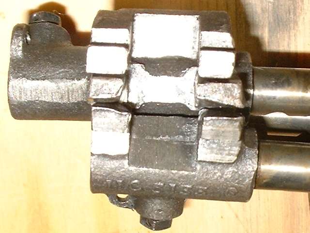
Now take a good look at the selectors (click for larger picture). This gearbox has seen a LOT of usage (maybe 200,000 miles), so the selectors are noticeably worn.
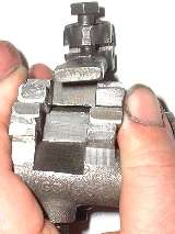
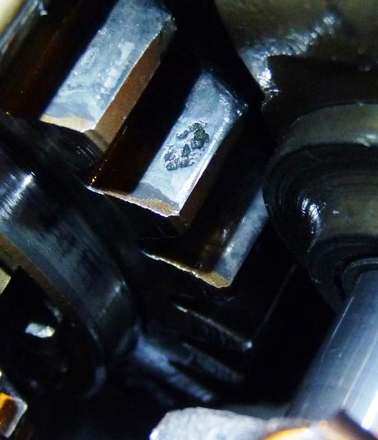
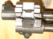 The top selector (with the wide stepped face) is for reverse, and shows very little wear. The middle selector (with thin fingers) is for 1st and 2nd gears. The bottom selector is for 3rd and 4th gears. These parts show substantial wear, but oddly enough it was still a pretty slick shifter. A small amount of wear on the selector parts can give it a smoother action when shifting, so don't be too concerned about these parts unless the wear is obviously excessive. If you wanted to put these parts back in service for another 100,000 miles or more, you might patiently weld up the worn surfaces and file or grind them back to flat with square corners. I would do it in a flash if I needed to, but so far I have enough good used parts. Or you might procure another used gearbox for cheap and use the best of the available parts. Photo at right above shows selectors with very little wear.
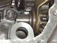
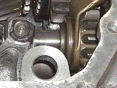
 Remove one special pin-nose bolt (with locktab) securing the reverse gear shaft (left). Slide the shaft out the back of the case, and lift out the gear. Inspect the gear for worn or chipped teeth. Some small chips on the beveled or rounded ends of the teeth is normal and is not a functional problem. This one appears to be low mileage with crisp beveled corners and no visible chips. The pressure faces of the gear teeth should be polished smooth with a little wear showing. If any one tooth pressure face is chipped or spalling (bits missing from the surface), then the gear should be replaced.
 Addendum March, 2021. -- The Reverse gear shaft does not have to be pulled out the back of the box. It can be tapped forward to be removed from inside the box (try not to drop it inside). Addendum March, 2021. -- The Reverse gear shaft does not have to be pulled out the back of the box. It can be tapped forward to be removed from inside the box (try not to drop it inside).
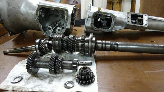
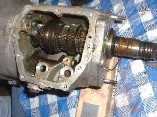 This has us down to the main case with the power transmission shafts and gears only. Next is to push the layshaft out either end of the case. Here, depending on what you have in mind for further disassembly or immediate reassembly, you may want to insert a thin steel rod in place of the layshaft (picture at right) to hold the thrust washers in place. An alternate method is to insert a foreshortened dummy layshaft, 5/8 inch diameter (PVC pipe or wood dowel) and 6-13/16 inches long (which will just fit inside the ends of the case). Once the layshaft has been removed, drop the laygear down into the bottom of the case where it will not interfere with removal of the gears on the mainshaft.
|