The MGA With An Attitude
REBUILDING THE MG GEARBOX - GT-203C
GT-203A - Test Drive Inspection
GT-203B - Open Inspection
GT-203C - Disassembly, External - (you are here)
GT-203D - Disassembly , Internal
GT-203E - Disassembly, Gear Clusters
GT-203F - Disassembly, Gears and Synchronizers
GT-203G - Reassembly
Disassembly, External
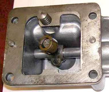
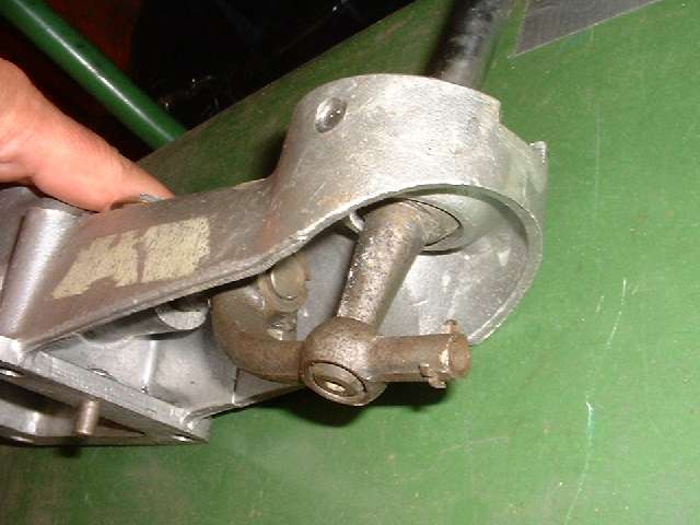
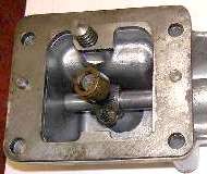
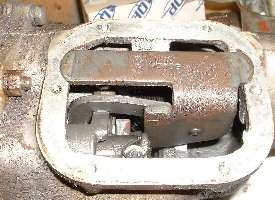
For disassembly, start by removing the side cover for internal inspection (previous page). Then remove the clutch release arm and front cover (save the bearing shims). Remove the top cover and remote shift extension assembly. Remove also the steel spacer plate beneath the remote shifter housing (first picture) as you will need extra space to rotate the remote control rod before the rear housing can be removed.
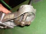
On the front lever of the remote control rod you should find a 2-piece split bronze bushing held together with a thin wire retaining ring (picture at right). Treat this like precious jewelry, as it has been unavailable as a replacement part for decades. These bronze bits may last indefinitely, but they are easy to lose. If you buy a used gearbox it may be missing the remote shift assembly, or the split bushing may be missing. The current substitute replacement bushing is molded from white plastic (Nylon or Delrin), and may be expected to break up from age deterioration in less time than anyone would like (several years if you're lucky). The original bronze part gives a nice crisp feel to the shifting motion. The nylon part (when it is working) gives a slightly softer feel to the hand lever. If the part is missing or broken (quite common for the nylon part) the lever motion gets very sloppy, and it may tend to get caught in a position of extreme motion for 1st, 2nd or reverse gear. The hand lever may even get trapped so it is stuck in gear and cannot be returned to neutral. The solution then is to remove the remote shift housing to reset the mechanism, and hopefully install a good split collet so it won't happen again.
Addendum 2005: One of our fellow hobby enthusiasts has recently produced a small batch of these split bushings, exactly as original issue. See article GT-120 (Split bushing for gearshift).
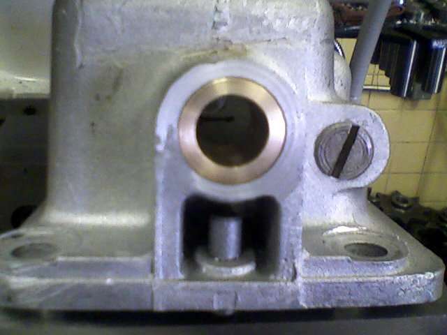
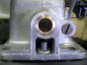 Check the bore holes in the remote shift extension housing where the rod slides in the aluminum housing. They should be a very close fit with little or no perceptible clearance. The ones inside of the main part of the gearbox are usually perfect. The rod in the remote control tower on the MGA gearbox can be a different story. This one is exposed to road dirt from underneath (remote control housing being open on the bottom), and the aluminum bores can get pretty sloppy. This housing can be bored out and bushed as standard machine shop procedure (if you can't find a good used one at reasonable price).
Also, check the spherical aluminum surface where the shift lever seats in the remote control tower. Somewhere way past 100,000 miles this surface gets badly worn, and the shift lever action gets sloppy.
 The flat top surface of the spherical part should sit about flush with a flat surface inside the housing. You could have the small bearing holes sleeved for repair, but fixing the worn spherical surface is more expensive. A reasonable fix here is a new (used) aluminum part. This is less of a problem with the 3-synchro MGB gearbox, as the remote shift mechanism is enclosed underneath on that unit. A badly worn ball socket can also be repaired with a machined insert. See article GT-206 (Remote shift housing rebuild).
The remote shift extension housing is (usually) the only part of the gearbox that may need any machine work for restoration. The rest of a gearbox rebuild is a fairly simple matter of disassembly, inspection, a few replacement parts, and reassembly.

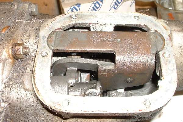
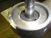
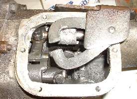
The picture here shows the spherical socket joint. At either side of the half-ball there is a non-rotation key slot and a round lateral keying pin in the housing. To remove the shift lever you may need to push the pin(s) back a little. Insert a thin blade between the tip of the pin and the base of the slot and tap it in to wedge the pin back just a bit. The slot is not as deep nearer the bottom of the ball, so the pins don't need to be retracted very far to allow the hand lever to lift out. If you're careful to get the pins positioned just right, you can leave them there where they will be effective keys and still allow disassembly. The hand lever is to be held in place by a compression spring, a stamped metal cover, and a large retaining ring.
 At the bottom end of the hand lever is a smaller ball which sits in a cylindrical hole in the rear lever. The rear lever has an extension at the back which carries an anti-rattle detent ball and spring secured with a split pin. If you pull the lever out the top, the small ball will likely be lost. That results in a nasty noisy rattling vibration of the hand lever at an engine speed right around highway cruising speed in top gear, which may drive you nuts on the open road. When the unit is in the car, this split pin lies above the gearbox tail housing and propshaft connection where it is generally inaccessible. So if you need to fix this problem, the shift extension assembly should be removed to gain access to the anti-rattle detent parts.
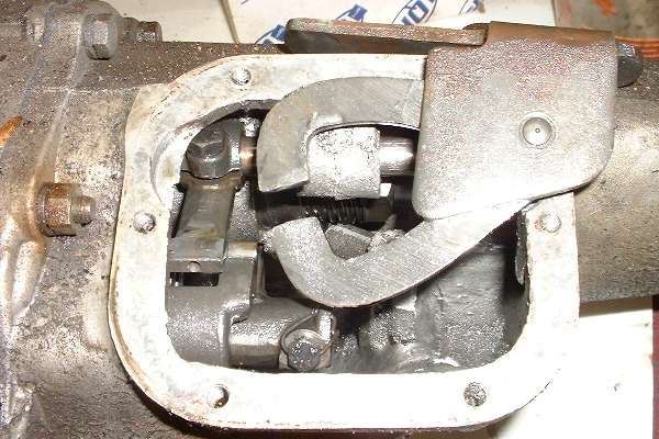
From under the top cover, remove the interlock arm assembly. This may be a bit of a puzzle the first time you do it. Pry the bracket from the top of the box and lift it up slightly. Rotate the remote control shaft to raise the selector lever. Move the interlock arm a bit to the side to disengage it from the three selector slots, pull it back to slip it away from the selector lever, and it should lift out easily. If at first you don't succeed, fiddle a little more. It does work (eventually). Be sure above mentioned spacer plate was removed to allow free rotation of the remote control lever.
An item to check at this point is security of the interlock arm on the mounting bracket. Refer to Confidential Service Memorandum MG/269. A loose rivet here can result in jamming in gear as the interlock arm may move to the right and hang up on the thicker part of the selector lever. If the interlock arm is loose it can be remedied by tightening the shoulder rivet.
The input bearing does not need to be removed from the input shaft unless the bearing will be replaced. Likewise the large retaining ring on the OD of the input bearing does not need to be removed (not ever). If you want to remove the large nut holding the front bearing, it will be more convenient to remove the input shaft first, and work the wrench later on the workbench when the input shaft stands alone (unless you have a really large and very long tube socket).
Removing the front main ball bearing from the input shaft requires removal of the large hex nut in front. This nut has a left handed thread, so it needs to turn clockwise for removal. With the input shaft removed form the gearbox, the shaft will be difficult to hold. You can make a spline wrench from an old clutch disc by extricating the splined hub from the assembly. You can improvise a handle for the spline wrench with a couple flat steel straps and a few bolts, see article TS-209.
You need to remove the rear flange nut on the 1600 type gearbox. If you don't find it convenient to hold the flange while removing the rear nut, you can shift the gearbox into two gears at once to lock up the mainshaft (after the interlock arm has been removed). Move one shift rod to engage 1st or 2nd gear, and another shift rod to engage 3 or 4th gear. Then go ahead and wrench off the nut to remove the rear flange. Shift it all back into neutral afterward. NOTE: The late model MGB gearbox does not use the interlock lever, but has interlock detents at the front end of the shifting rods.
Remove the speedometer drive spindle housing and small gear from the bottom/side of the rear housing. If left in place this may interfere with removal of the rear housing on the 1500 type gearbox, because of the locktab washer at the back of the helical speedometer drive gear (but may not interfere with the 1600 type gearbox). Also remove the shift extension spacer plate from the top of the rear housing (mentioned twice before). If left in place this will interfere with sufficient rotation of the remote control shaft.
Next remove bolts and part the rear housing from the main housing. One nut on the top stud cannot be fully removed until the rear housing is withdrawn slightly. If it's a little stubborn it may require a little whack with a plastic faced dead blow hammer, or a gentle thump with a 2 pound hammer and a bit of wood in between to protect the aluminum housing. Rotate the remote control shaft to move the selector lever downward out of engagement with the selector slots. Then the rear housing may be pulled off to the back. If you have trouble here, refer to removing the top spacer plate (repeat over and over) and the speedometer drive spindle.
If the selector lever does not quite clear the bottom gate, check to see if the tip of the bolt securing the lever on the shaft might be touching the housing. I have heard of this condition only once so hopefully it is rare, possibly a result of incorrect bolt being too long. Loosening the pinch bolt a turn or two may be enough to solve this issue. A longer term solution may be to shorten the tip of the bolt slightly.
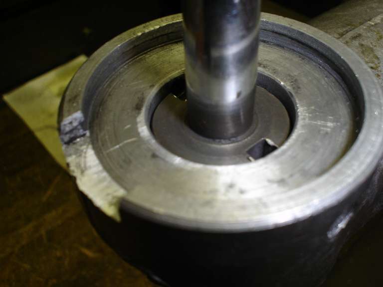
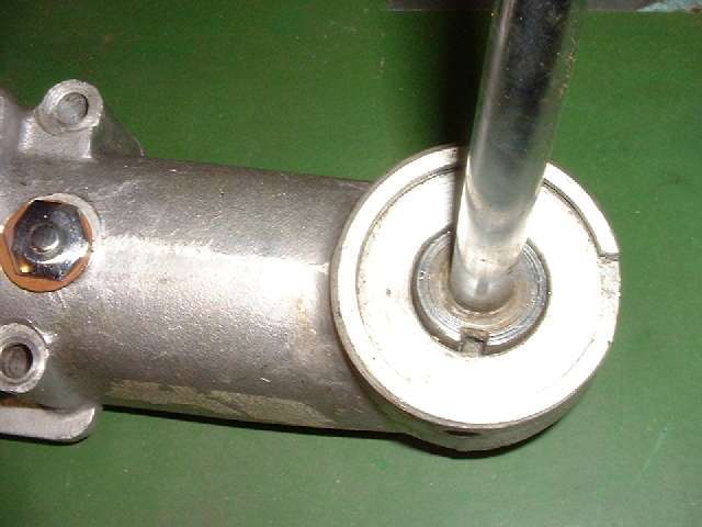
 The 1600 type gearbox has flanged output and a larger ball bearing in the tail end. This bearing is sometimes reluctant to slide off the tail shaft after removing the flange. For this you can withdraw the rear housing a small distance from the main housing, then insert some wood spacers between the housings, followed by a good thump on the end of the tail shaft to drive it forward through the rear bearing. Otherwise you need pry bars between the front and rear housings, but be careful not to mar the gasket seal surfaces on the alloy case. Someone has made a special pupper tool for this appllication (see Tools article TS-219)
The rear housing carries the rear bearing and the rear seal, which are more conveniently removed after the housing is off. For the 1600 type gearbox, remove the rear seal first, then remove a large circlip and withdraw the ball bearing. The bearing is secured with a snap ring (circlip), but the bearing has space allowed to float slightly fore and aft in the housing. If the bearing is in good condition it is not necessary to remove it from the housing.
|