The MGA With An Attitude
REBUILDING THE MG GEARBOX - GT-203G
GT-203A - Test Drive Inspection
GT-203B - Open Inspection
GT-203C - Disassembly, External
GT-203D - Disassembly , Internal
GT-203E - Disassembly, Gear Clusters
GT-203F - Disassembly, Gears and Synchronizers
GT-203G - Reassembly - (you are here)
Reassembly
Reassembly is the reverse of disassembly, with a few additional details to attend to. Oil all parts during assembly. On the mainshaft be sure the bronze bushings have the oil supply holes aligned, and the front thrust washer is securely locked in place. The oil groove in the front locking washer goes to the rear, facing 3rd gear. If you are particular you can (and should) check end float of 3rd gear (and readjust with the thrust washer thickness if necessary).

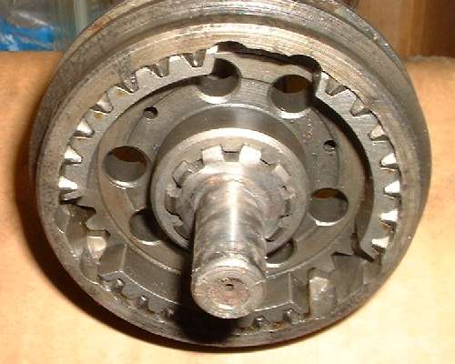
The 3-4 sliding hub is asymmetrical, so it needs to be properly oriented (long center hub extension forward). If the 3-4 sliding hub is reversed, the input gear will be pushed forward, and the front bearing will not quite seat in the main case (dead giveaway). Place synchro ring against 3rd gear, then slip the 3-4 sliding hub on the mainshaft, followed by another synchro ring.
Click for Layshaft Bearing Assembly Instructions - (offsite 0.8-MB pdf file).
Place the laygear (with bearings) in the bottom of the main case first. Insert the thrust washers at this stage (larger washer at the front larger end of the gear) and run a thin metal rod through the assembly to retain the thrust washers, while keeping the laygear near the bottom of the case. An alternative is a foreshortened dummy layshaft to hold the thrust washers in place (as mentioned in the prior page on disassembly).
The laygear should have a small amount of end float (when dry) to accommodate oil film on both sides of both end thrust washers. Total end float (when dry) should be 0.003 to 0.006-inch. When oiled the end float should be in the range of 0.000 to 0.003 inch. This is adjusted by changing the rear thrust washer to one of different thickness.
Laygear thrust washers:
Position- Moss# - BMC# - Thickness
Front- 461-114 - 1G3576 - 0.1537" thick
Rear - 461-600 - 1G3577 - 0.155" thick
Rear - 461-610 - 1G3578 - 0.157" thick
Rear - 461-620 - 1G3579 - 0.160" thick
Rear - 461-630 - 1G3580 - 0.163" thick
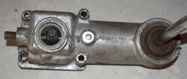
Have the input bearing assembled on the input shaft with locktab washer and retaining nut, and the large snap ring on the OD of the bearing. Install the roller set (18 rollers) inside the back end of the input gear. Use bearing grease to hold the rollers in place during assembly. Insert the input gear through the front. Push the front bearing home to seat the snap ring against the face of the case. If you knock any of the spigot rollers out of place during this process you get to remove the input shaft and start over (and the long pencil magnet comes in very handy).
On 5/13/2023, MJ & A Stead wrote:
"The loose roller design has always been a pain to work with sticking in with grease, but I resolved this for myself 60 plus years ago. Here is how.
 Take the clean dry rollers one at a time and with a small powerful magnet stroke the roller along its length 3 or 4 times. The roller will be magnetic now and can be placed in the input shaft where it will stay stuck to the wall of the bearing surface. Repeat for all required rollers. Apply oil, as grease blocks your view of the area when inserting tip of mainshaft, and even if a roller is slightly disturbed it tends to get drawn back into place by the magnetism. If you do need to push a roller back into place yourself the use a non magnetic item such as a handle of a long thin artist type brush is effective. As soon as it gets near the other rollers it will be happy to join them and pop back where it belongs. Take the clean dry rollers one at a time and with a small powerful magnet stroke the roller along its length 3 or 4 times. The roller will be magnetic now and can be placed in the input shaft where it will stay stuck to the wall of the bearing surface. Repeat for all required rollers. Apply oil, as grease blocks your view of the area when inserting tip of mainshaft, and even if a roller is slightly disturbed it tends to get drawn back into place by the magnetism. If you do need to push a roller back into place yourself the use a non magnetic item such as a handle of a long thin artist type brush is effective. As soon as it gets near the other rollers it will be happy to join them and pop back where it belongs.
Obviously this works on any other setup with loose rollers, such as layshafts that do not have caged bearings. (Rootes gearboxes for example). Works perfectly on caged bearings if they do not have retaining clips and persist in falling out of place when the component is being installed". -- Regards, MJS
With the 3-4 sliding hub and synchro rings in place (correct orientation please), insert the mainshaft assembly through the back of the main case. Align the spigot end of the mainshaft to enter the roller bearing race in the input gear, being careful not to knock any of the needle rollers out of place. Take a good look at the face of the rear housing to know where the alignment pin for the bearing carrier needs to be oriented. You can use the joint (paper gasket) as a guide to properly align the dowel pin. If the gasket is dry and shrunken too small you can soak it in water for a minute to make it expand back to original size. You might even use the rear housing temporarily as an alignment guide to push the mainshaft assembly into place in the main housing. Otherwise install the mainshaft first, then offer up the rear housing for alignment reference, and use a punch and light hammer to tap on the alignment pin, and rotate the bearing carrier plate to bring the pin into alignment with the guide hole in the rear housing. Push the mainshaft forward to fully seat the bearing carrier plate flush at the back. This is where alignment marks mentioned on the prior page may save some time.
With mainshaft and input shaft installed, lift the laygear into position and insert the layshaft while withdrawing the thin guide rod. This may be much easier to do if you stand the unit vertically on end so the laygear and thrust washers will stay put without the shaft in place. A long socket extension works well to reach through the bore and align the laygear and thrust washers concentric to the bore in the case. Insert the layshaft (stepped end forward), and push it home to be flush at the back. Rotate the layshaft to align the step at the front with the mating socket in the front cover. The flat on the layshaft should be facing the mainshaft to match the mating flat in the front cover.
Install reverse gear (small side forward) with shaft, pin bolt and lock tab.
Insert three shifting forks, 1-2 fork, then 3-4 fork, then reverse fork. Slide the shift rod assembly in from behind, seating the detent block on the back of the main case, and securing the forks to the rods with the pointed bolts. Note that the pointed bolts must enter and seat into alignment holes in the shift rods. If the locking bolt misses the hole the shift fork will be out of position on the rod (misaligning the sliding hub) and shifting will not work properly. Use a toothed lock washer and jam nut on each one. Tighten the bolt first to secure the fork on the shaft, then tighten the jam nut to guarantee that the bolt will stay put during the most abusive service. Also install the bolts to secure the detent block at the back. Install the oil pump spool (helical grooved spacer) on the mainshaft, followed by a woodruff key and the speedometer drive gear. For the 1500's secure the oil pump spool and speedo drive gear with a locktab and large nut. For the 1600 type gearbox, place the long tube spacer on the output shaft to secure the oil pump spool and speedo drive gear. Note that these parts will remain loose until near end of assembly when the rear flange is installed.
Have the rear housing prepared with a new rear mount (if necessary) and a good tail bearing and rear seal already installed, and the selector rod with levers in place. The external seal for the early 1500 box is a bit expensive but generally is still available. Push this seal over the tail end of the housing and stake the shell into the groove in the housing in two to four places. If you're a little suspicious of leaks you might use a bit of sealant between the seal shell and the aluminum housing.
The internal seals for the mid 1500 and later models are reasonably priced and easy to get. Original seals were quite thick leather and rubber parts. Modern replacement seals will likely be a thinner ordinary rubber double lip seal with a garter spring inside (not necessarily better, but serviceable). Press those in to be flush at the rear of the case. They do not need to be pushed to the bottom of the counterbore.
Gaskets are pretty cheap. Buy the whole gearbox gasket set if you can. Install a new paper gasket and slide the rear housing into place, positioning the front selector lever within the selector gates, and aligning the pin on the center bearing carrier to the hole in the rear housing. If the dowel pin does not quite line up with the hole in the rear housing, you're shooting at an oil flow hole. Rotate the bearing mount to put the pin in position for the correct mating hole. Two hex nuts with lock washers (at least the top ones) must be installed on the threaded studs before the rear case is fully seated. Install bolts and tighten to secure the rear housing.
Note that the 1600 type gearbox has the ball bearing in back. This should be a slip fit on the shaft and a tighter fit in the housing. When the bearing is installed in the housing with a snap ring there is space allowed for the bearing to float a little fore and aft in the housing. In final assembly it does not touch either side of the outer race. The bearing might sometimes be a rather tight fit on the shaft, so forcing the rear housing onto the shaft could push the mainshaft forward, resulting in pushing the input shaft out the front. If this is a problem you may want to install the front cover first, at least temporarily, so you can push the rear housing and rear bearing into place over the mainshaft. Once in place you may need to tap the rear bearing forward in the housing to allow installation of the rear flange.
Once the rear housing is in place you may install the speedometer drive pinion gear shaft and housing at your convenience (even in the car). This should have a fiber washer for sealing. You might also replace the speedometer drive spindle seal, knowing that this is below oil level in service. If oil leaks out here it can be augured up the flexible drive cable to ultimately slime up the back spool and innards of the speedometer.
If your gearbox front cover is an original MGA 1500 or 1600 part, it won't have a rubber seal. But it is common practice to fit a front cover from a late 1600 MK-II gearbox which has a rubber seal. The early MGB front cover will fit on the MGA gearbox, but it has the pivot point for the clutch throw out arm in a different location to accommodate the thinner MGB clutch pressure plate and the MGB release arm. This cover uses the same seal as the late MGA part. Any cover with the seal and the seal itself will work with your original input shaft.
The Workshop Manual refers to special service tool 18G598 - Gearbox front cover centralizing tool. It mentions this in reference to later front covers with oil seal, but I don't quite see the point. and I think the book may be incorrect here. Early cars had no rubber seal, just the mechanical scroll seal in the front cover. Running clearance there is smaller than clearance around the mounting bolts, so a centering tool may be necessary to prevent mechanical contact in the scroll seal area. Later covers with the rubber seal shouldn't care, because the rubber lip has enough flexibility to accommodate a lot of misalignment, so no special tool is necessary. I will stand on that logic until someone gives me some reason to think otherwise. I always convert the earlier unit to the later front cover with rubber seal. I have never used the special centralizer tool, and no problem with front seal leaks.
Install the front cover with bearing shims and paper gasket (and a new rubber seal if it uses one). This is just a little tricky if you want to check, verify, and/or adjust the bearing shims. The book just says to reinstall the original shims, but I find that these often get mutilated somehow and need replacement(s). The idea is to shim to minimum clearance to eliminate end float of the bearing in the housing. But do not install too much shims, or the cover will not seat and the paper gasket will not seal. It helps immensely to have a good depth micrometer. Tap the bearing back to seat the outer ring solid against the housing. Measure the extension of the outer bearing race ahead of the housing face. Measure depth of counterbore in the front cover, and the thickness of the paper gasket. Starting with depth of counterbore, add gasket thickness and subtract the bearing extension. Stack outer race shims to that thickness or slightly less. Shims are available in 0.002" increments, so the ideal end float would be 0.001" to 0.003". Good luck with the measurements. If in doubt about the correct dimension, make the shim stack slightly thinner. Stick the shims in place with grease during assembly, and secure the front cover.
Addendum, February 6, 2013:
Martin in western Canada offers this suggestion:
"To figure out shims for tranny input shaft, I put several short pieces of broken piston ring, not necessarily MG, only to get consistent thickness, on bearing face using grease to stick to it. Then I put tranny cover and gasket on and hold it with several bolts (do NOT tighten it down). You measure with feeler gauge space between tranny body and cover minus ring thickness and figure out shims needed".
This should work well, as thickness gauges may be more accurate than a dial caliper. Don't forget to allow for thickness of the paper gasket. That is, subtract thickness of the gasket from the feeler gauge measurement, or have the gasket in place when measuring.
Addendum, March 4, 2024:
Marcus T in Ocean Shores, WA, USA wrote:
"After I set the input shaft assembly into the case, I used Plastigauge in 3 spots (12, 4 and 8 o'clock positions) to check the clearance without any shims, with the gasket and the cover installed and tightened to the proper torque. Loosened and removed the cover and measured the clearance and added shims (.002 and .004?) as needed".
You can install the clutch release arm, release bearing and rubber boot at your convenience, any time before mating the engine to the gearbox. Inspect the pivot bolt and bronze pivot bushing, and replace if worn (which they usually are).
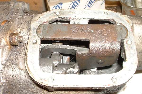
At top of rear housing, install the interlock arm assembly. Tap the bracket down firmly in place, flush on top, and install the cover. Orient the cover with the rectangular bump to the front over the moving interlock arm, as the arm rises slightly above the case during shifting into reverse. Install the cover with a new gasket. Note that pictures in the catalogs and factory parts list incorrectly show the cover backward with the bump to the rear.
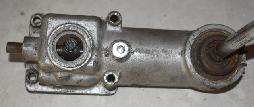
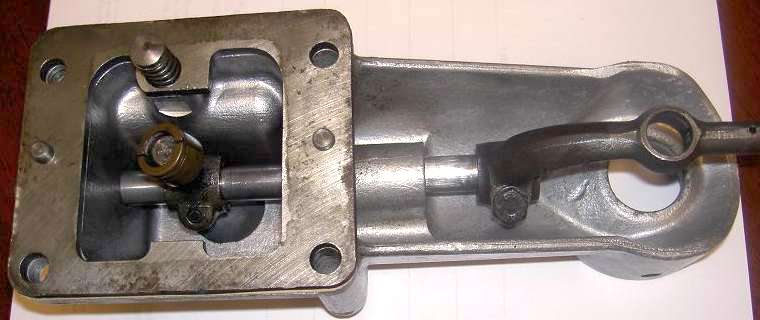
Install the spacer plate for the shift extension with two gaskets and alignment pins. Align the inside tab and hole in the plate with the spring plunger on the remote shifter (see picture). Installation of
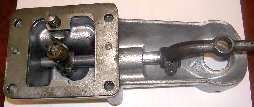 shifter is optional, as it likely needs to be removed for installation in the car (or maybe for shipping). When installing the shift extension, notice that the tapped holes in the top of the rear housing may be either coarse or fine thread, depending on time of original production. Do use the correct bolt threads to match. If you bugger these up you get to install Heli-Coils for repair, in which case you can use fine threads.
Whenever you are installing the remote shift extension, pay attention to correct installation of the split bronze bushing on the bottom end of the front arm, and seating of that bushing into the nest of the rear arm on the selector shaft. It can be a bit of a fiddle to get the bushing into the hole in the arm. Do NOT knock the bushing off the ball and drop it into the gearbox.
As a point of interest, if you had disassembled the remote shifter assembly, or if the pinch bolt in the front control lever was loose, you would need to remove the core plug on top of the housing to have access to the pinch bolt on the front lever.
Before closing the box, check that the shifter works properly to engage all gears. Turn the input shaft and verify that the output shaft turns in each gear (including reverse). Oil everything inside liberally, especially if it may be left in storage for some time.
Install the side cover with a new gasket. Three screws at top are flat head screws requiring special conical countersink lock washers. One screw down from the top at the back of the side cover has a through hole to the inside of the case. This one should have a fiber washer for sealing, plus a flat washer and lock washer. The other bolts get lock washers only. The top fill dipstick has a felt seal, which may not be available separately. Now you remember that little split pin in the bottom of the bell housing? Good idea to ensure that it is still in place, and a little loose. A bit of vibration with the split pin keeps the drain hole open.
The 1600 type gearbox (with flanged output shaft) could be filled with oil before installation. Just don't tip it onto the right side or upside down, and do not stand it on end with nose down (or the oil could spill out from the dipstick hole or around the input shaft). Do not put oil in a gearbox which is to be shipped. Do not try to put oil in the 1500 type gearbox before installation, as it would run out the back until the propshaft is installed. But after installation, do be sure to put oil in the gearbox before running the engine.
That's about it. The MGA and MGB gearboxes are pretty easy to work on. Just don't lose the spring loaded bits. It's frustrating to have to place an extra parts order for one little spring and two steel balls just because they went flying under the bench somewhere. And that's usually on the last day when you want to finish the job, so it makes you wait another week or more for the last few parts. It is not particularly difficult to rebuild an MG gearbox, and you'll get one hell of an ego trip when it's finished and running again.
Addendum Nov 2013:
Harrie van Winsen in the Netherlands sends this link to a short video on YouTube showing the gearbox running through the gears after assembly. www.youtube.com/watch?v=IIqAy55iadA
On 2/25/2016, Ed Faille in Auburntown, Tennessee, USA wrote:
"This procedure was AWESOME! I had a great learning experience and now have a nice overhauled non synchro gearbox in my early MGB. It took a while, but it's done".
|
 shifter is optional, as it likely needs to be removed for installation in the car (or maybe for shipping). When installing the shift extension, notice that the tapped holes in the top of the rear housing may be either coarse or fine thread, depending on time of original production. Do use the correct bolt threads to match. If you bugger these up you get to install Heli-Coils for repair, in which case you can use fine threads.