The MGA With An Attitude
MGA Guru Is GOING MOBILE - (March 16 - March 31, 2026)
Monday, March16, 2026:

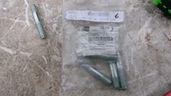
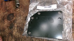
Start the day with adding a new Part Numbers tech page for the 6K639 Screw with captive washer for securing the oil sump on MGA engines.
Going on3-pm, tracking says the new crankshaft and radiator are officially late. Getting too late in the day now, so we will not be reassembling the engine until tomorrow morning. Finally at 5-pm the stuff was delevered, which was about what we were allowing for, so making plans for engine reassembly tomorrow.
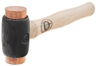
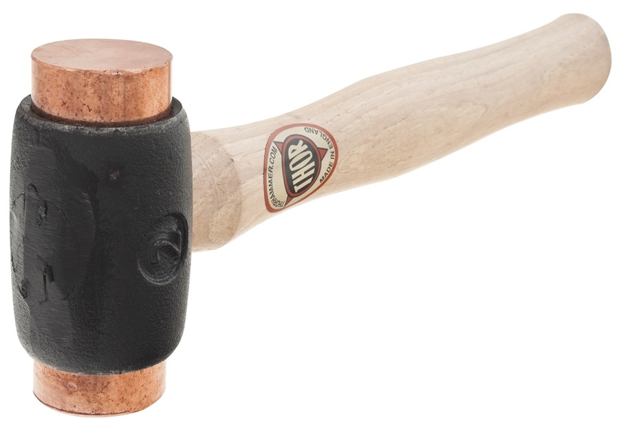
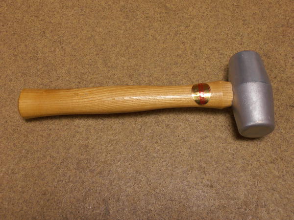
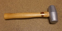 First item on theTraveling Tools kits for MGA Part Numbers list is the 11B5166 Thor copper faced wheel knock-off hammer. This was also used for the Twin Cam cars. In mid 1600 production this was changed to 88G329 Simmons solid lead hmmer.
Tuesday, March17, 2026:
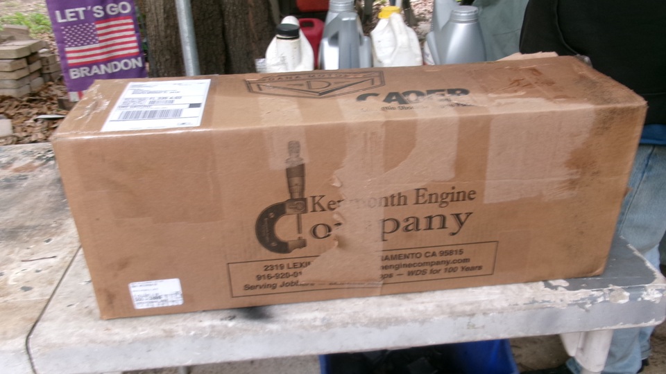
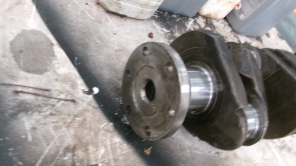
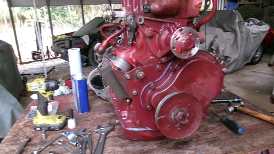
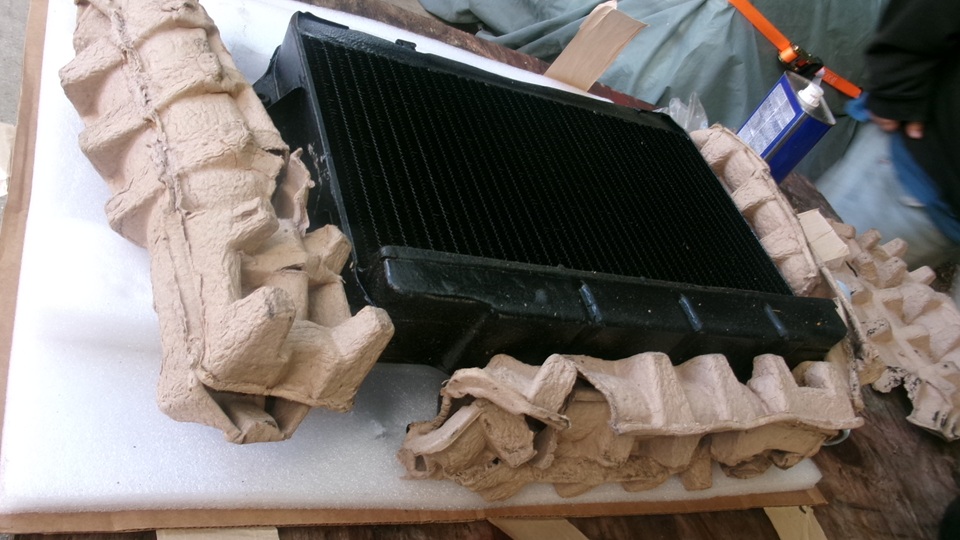
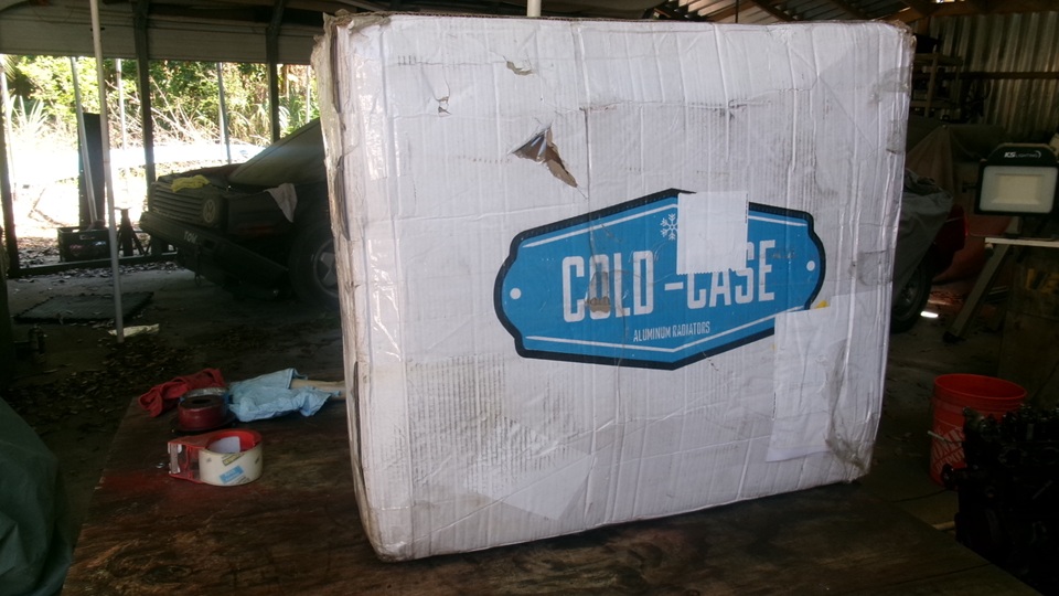
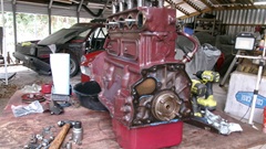
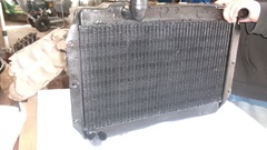
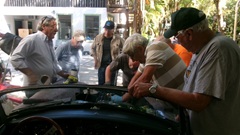
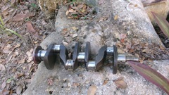
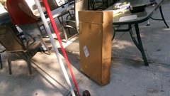
Cool morning, quick run to Walmart for engine oil, have breakfast, side trip to Napa for oil filters, then on to Tech Central by half past ten. Collect the booty that arrived late yesterday, our freshly re-cored cell core radiator, which we will leave in the box until we need it in a couple of days, and the fresh crankshaft with M.010/R.010 older regrind that polished up nicely, read to go. Pull that out of the box, check everything end to end, and oil up the journals ready to install.
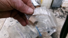
Well it was missing a few things. Knock the front end woodruff keys and flywheel studs out of the old junk crankshaft to install here, along with some crank sprocket shims, and install a new spigot bushing.

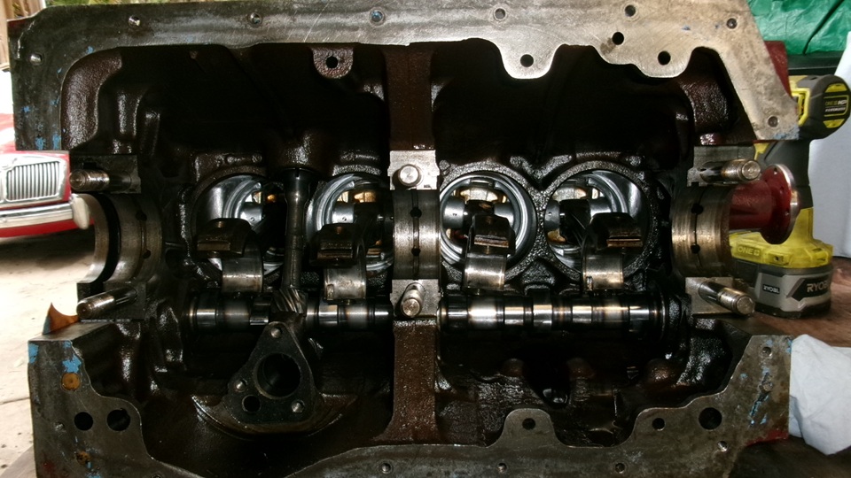
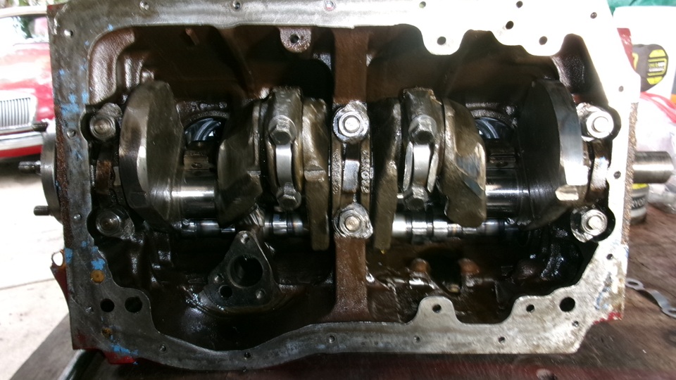
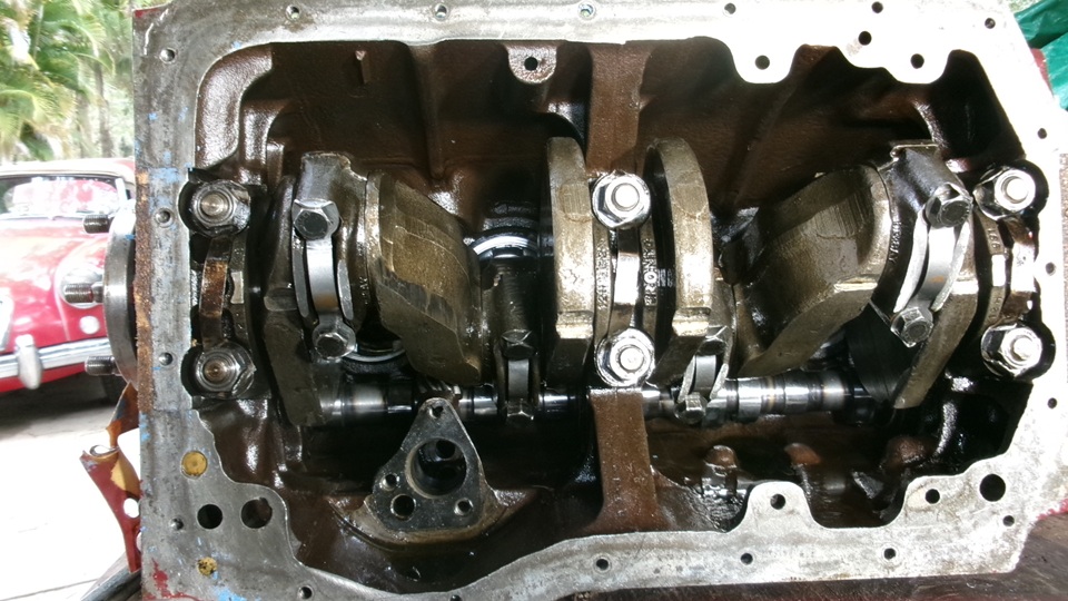
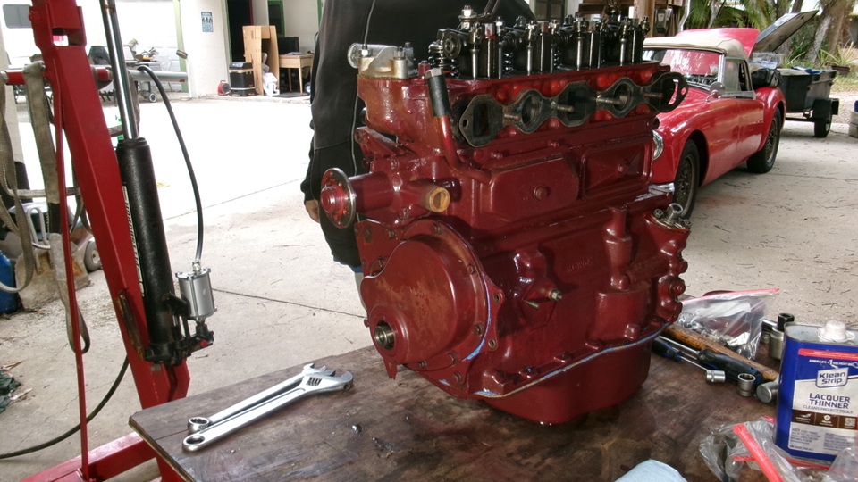
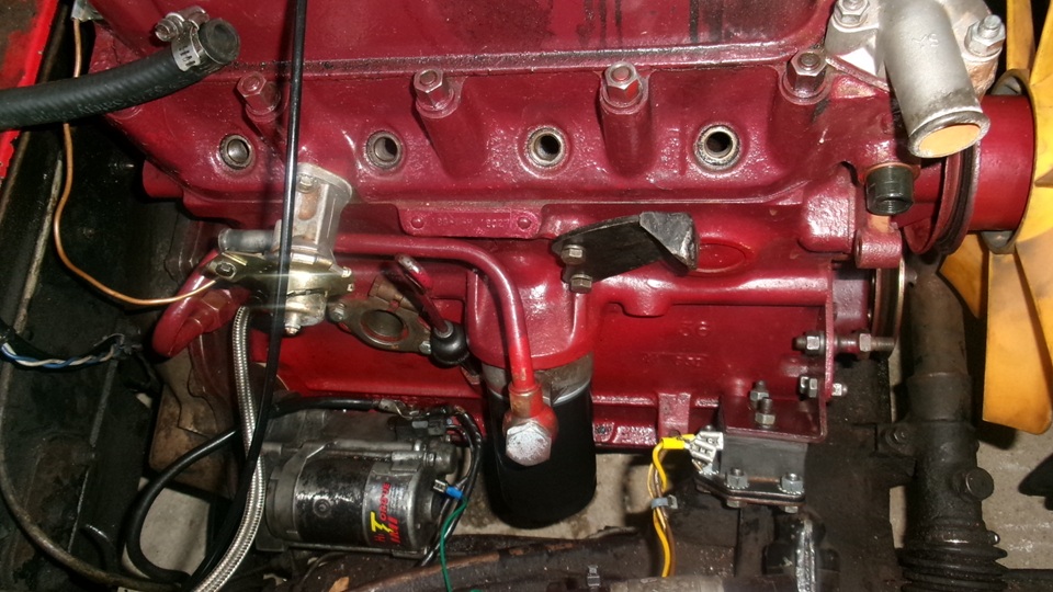
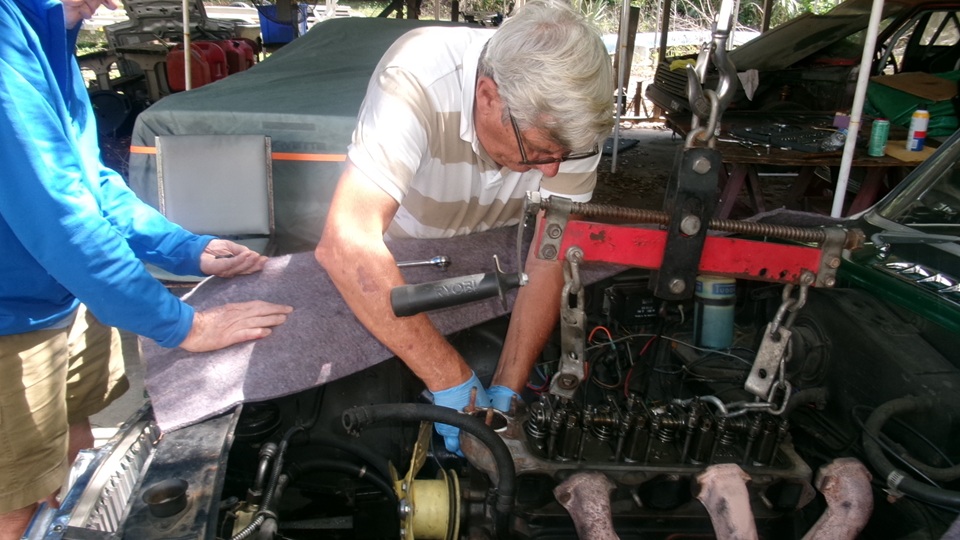
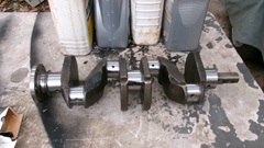
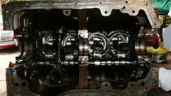
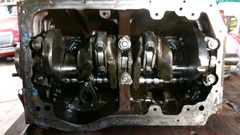
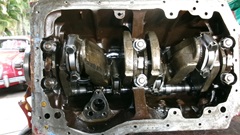
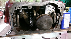
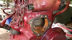
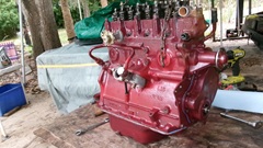
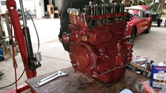
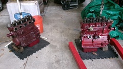
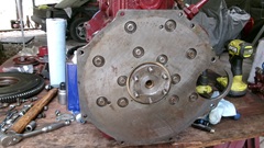
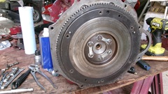
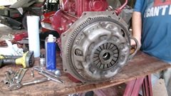
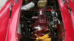
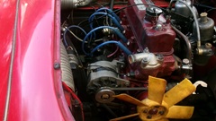
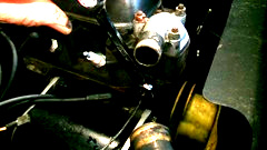
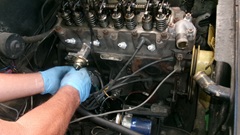
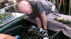
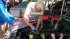
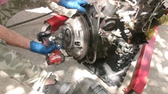
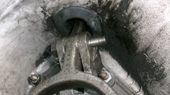
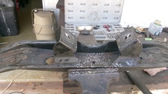
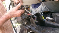
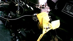
Remember the bottom of the engine with pistons still in it, crankshaft missing? Well, install three main bearing half shells, press the crankshaft into place, install upper thrust washers, then the center main bearing cap with new bearing half shell and lower thrust washers (all well oiled). Then the front and rear main caps with new half shells (well oiled),tapped squarely flush with front and rear surfaces of the block. install the main cap locktabs (which seem to be unique to MGB engines), torque down the big nuts while periodically turning the crankshaft to assure it turns freely. Second picture below shows #2 and #3 con-rods reconnected with new bearings and fresh locktabs. Last picture below shows all four con-rods connected, torqued up, and all locktabs set.
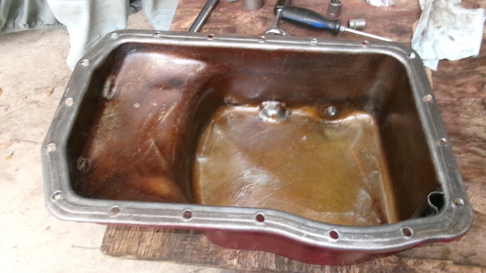
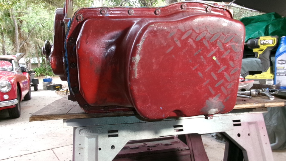
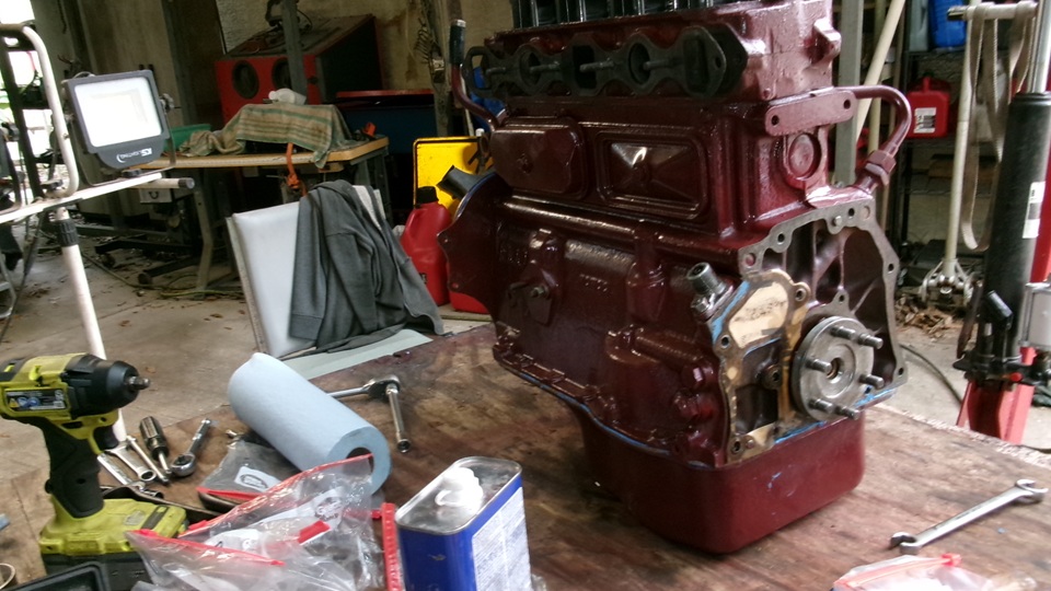
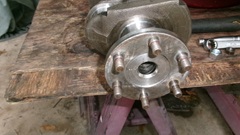
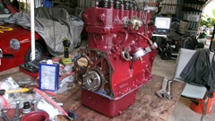
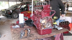
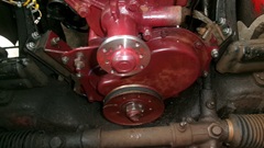
Pick the engine up and set it up straight to install the front plate, camshaft retaining plate, timing chain and sprockets, cam nut with locktab, chain tensioner, oil thrower ring and timing cover (using the crank pulley to center the front seal before tightening the cover bolts). Then back on its side to install the oil pump and pick-up screen. Clean away all remnants of the old pan gasket, hammer flat all of the bolt hole protrusions, and clean the sump well before gluing on a new cork pan gasket.

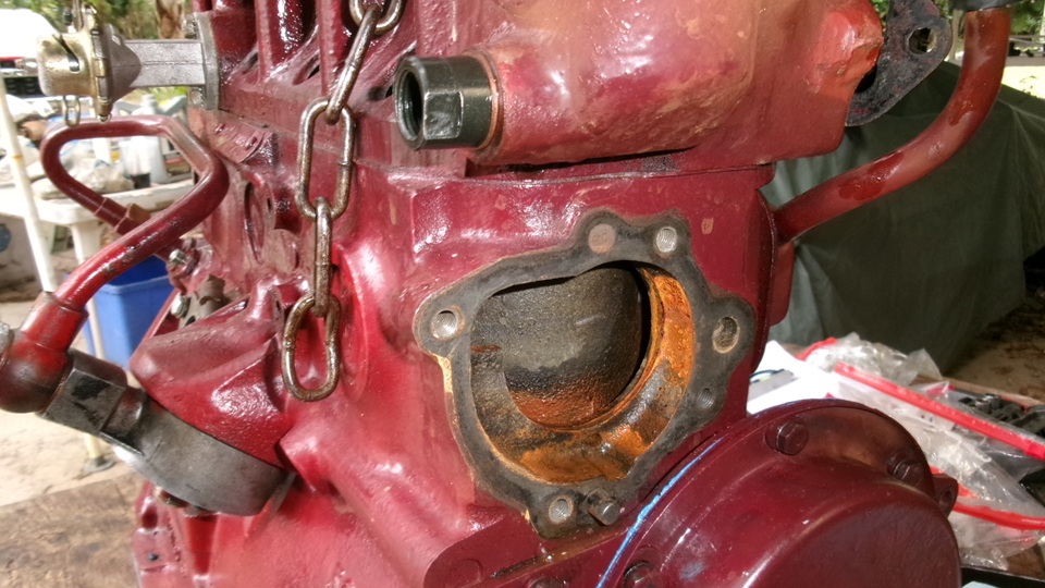
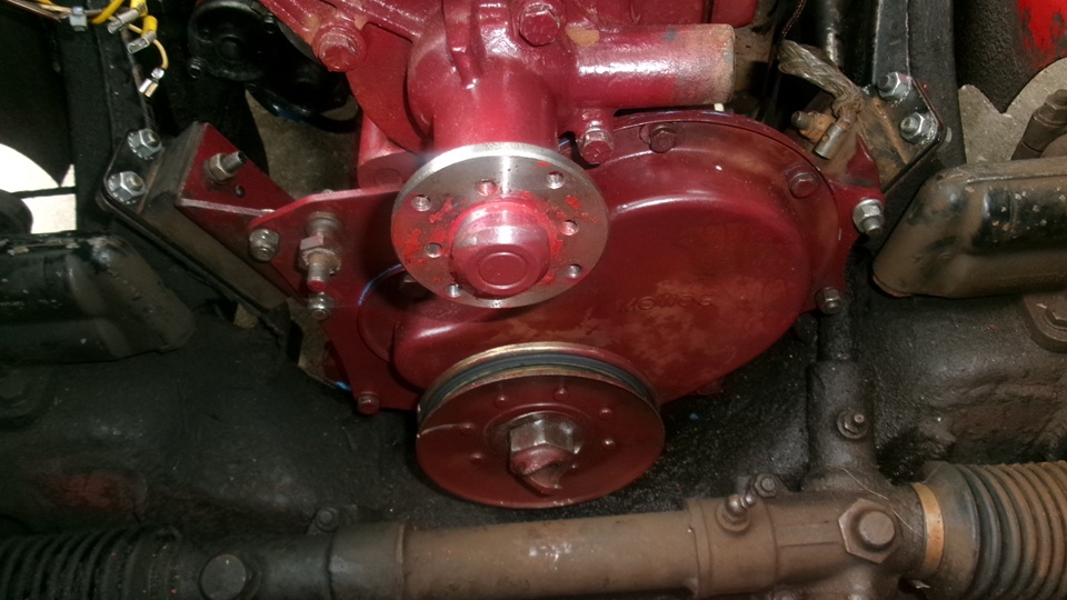
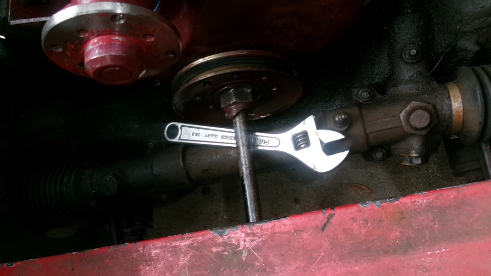
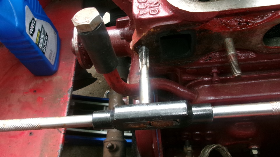
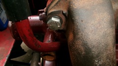
We kept one of the cork main cap seals, replaced the other one, and installed the sump with 19 screws, snugged up until the cork gasket began to bulge a bit at the edges. We had procured a second adapter for the temperature sensor port so we could leave one on each engine. Had to remove the water pump temporarily to have space there for wrenching the adapter tight using a new copper washer, then reinstall the water pump (easy with only four bolts).
That's it, ready for the next engine swap. The rest is just a quick walk around to to be sure we didn't miss anything. The rear plate, flywheel, clutch and engine mounts will come from the car when the Magnette engine comes out tomorrow.

Set the engine on a rubber mat on the floor and cover it up for safe keeping over night. Stash the new radiator box back under the canopy, in case it might rain. Clean up and pack the tools away before heading off for late lunch at 4:30-pm. Not bad for a casual 6-hours work with no rush. Tomorrow will be a longer work day. Updating inventory and wish list late night.
Wednesday, March18, 2026:
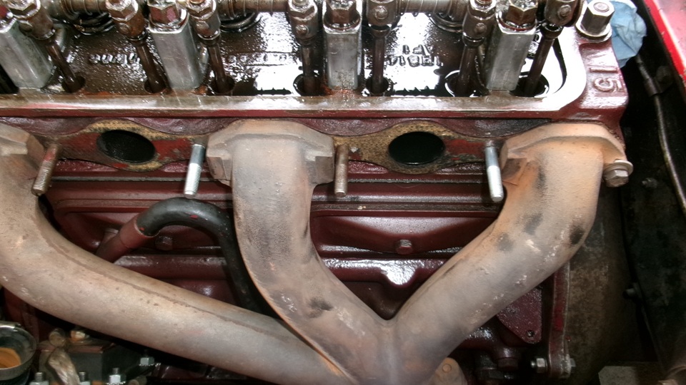
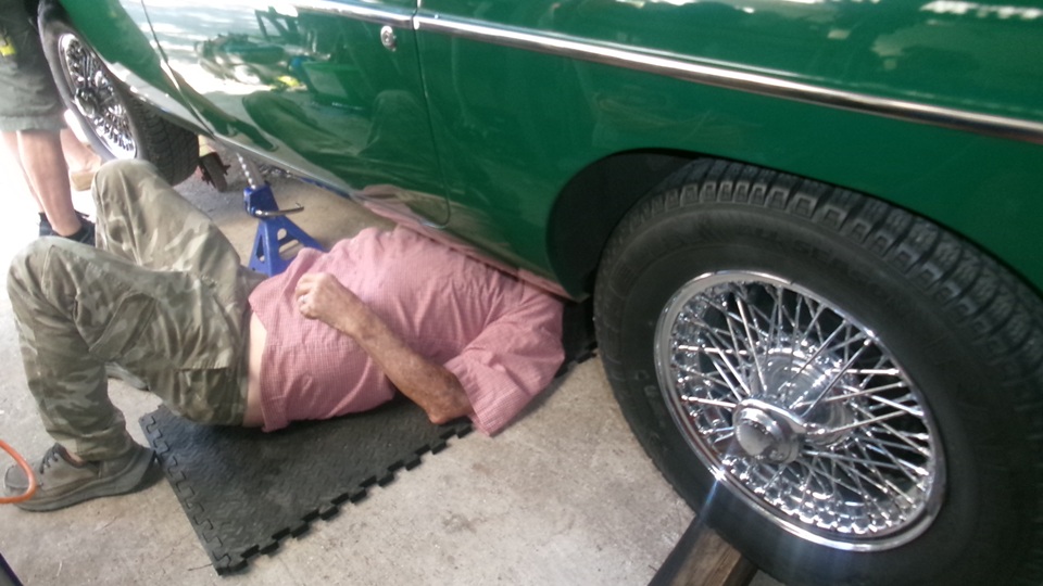
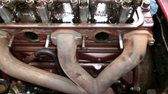
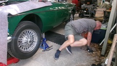
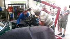
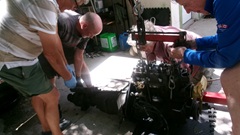
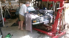
A little after 10-am we were on the path to removing the Magnette engine from the MGA. Remove the bonnet,then the radiator, fan, alternator, distributor, battery cables from starter motor, top starter bolt, two top bellhousing bolts, and the carburetors. The first oops was two manifold studs came out with the nuts, with the stud threads damaged. We carry spares,in fact we had eight, so no big deal to replace two and put the others back into the Magic Trailer. We intend to keep the Magnette engine in as good condition as possible (even though we only borrow it). -- With the car jacked up, navigator spent an hour on his back undoing the exhaust downpipe and brace, some lower bellhousing bolts and the bottom starter bolt, while I was undoing engine mounts bolts, breather "J" pipe, oil filter, oil pressure signal hose, battery cables and starter motor.
By 1-pm the engine was out, on the bench, and being stripped of parts needed for the swap. Off came the crank pulley, engine mounts and brackets, alternator bracket and adjuster pillar, clutch, flywheel and rear plate (quick work with power tools).

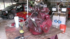
Set the Magnette engine on a rubber pad, and pickup the 1800 engine. Reassembly is the reverse of disassembly.
Install rear plate, flywheel, clutch, engine mounts and crank pulley, alternator rear bracket.

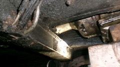
It didn't take long to slip the 1800 engine back into the gearbox and do up a few bellhousing bolts and the starter motor. Then we were into installing spacer plates under the engine mounts. We did this a few years go in California, and it took four hours of fighting with the engine mounts to get the bolt holes to line up. A year and a half ago in West Virginia, while we were first installing the 1800 engine, we left the spacer plates out for lack of time. Now determined to put them back in again, it only took us an hour and a half this time, as opposed to the normal half hour to install the eight bolts. But it is worth it, as it raises the engine up at lest 3/8-inch. This makes it much easier to access the five small bolts at front of the oil pan, if you need to R&R the sump without removing the engine. And it makes it so much easier to use the Starting Handle (
hand crank).

Then the second oops of the day, while installing the exhaust manifold we stripped the threads for the front manifold stud, where we commonly install hex head bolts in place of the studs. That makes it easier to R&R the head without moving the exhaust manifold. Only a small delay to drill out the remnants of the stripped threads (with 21/32" drill bit and small Vice-Grip), then tap it out to install a Heli-Coil, and put it back together with a new bolt.


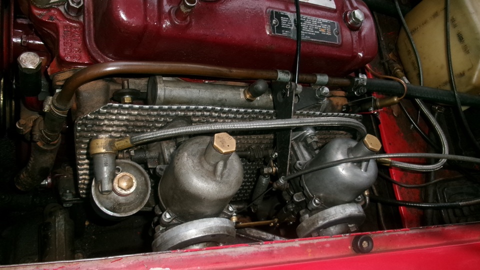
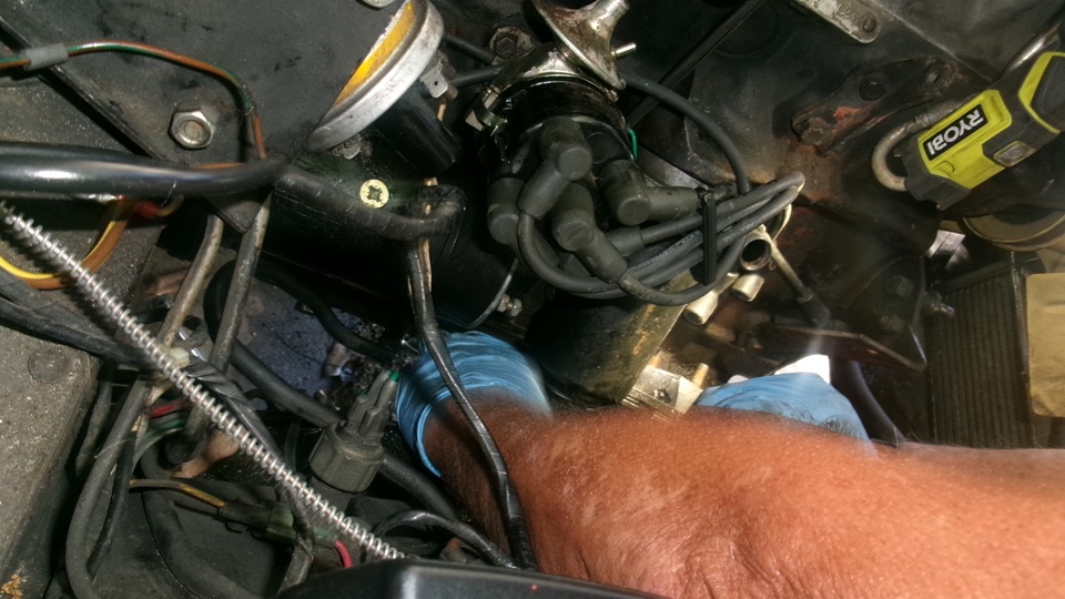
While Navigator was under the car for another hour installing exhaust pipe bolts and brace, I was installing the carburetors and linkages, fuel and heater hoses, cooling pulley and fan, valve cover, oil filter, reconnecting battery cables and putting oil in the engine. Woo-hoo. Battery switch on, and crank it for a minute (plugs out) to get oil pressure. A good place to stop for the evening, as it was finally getting dark at 7-pm. Time for late lunch, and to get these photos and notes processed and uploaded.


Thursday, March19, 2026:
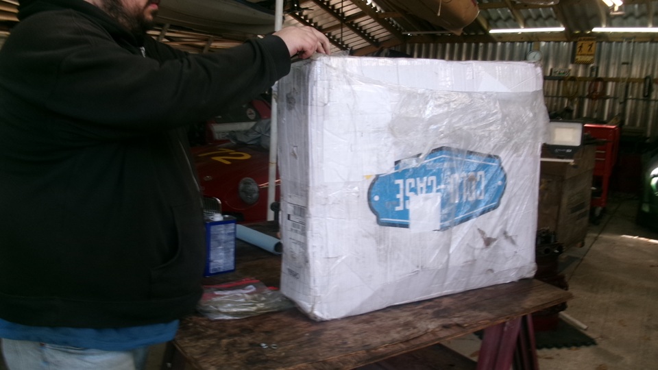
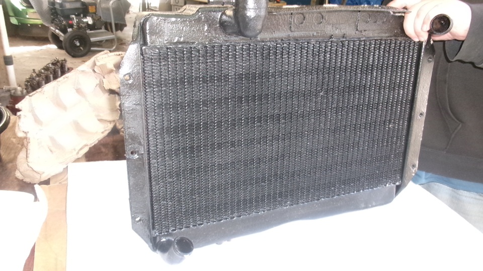
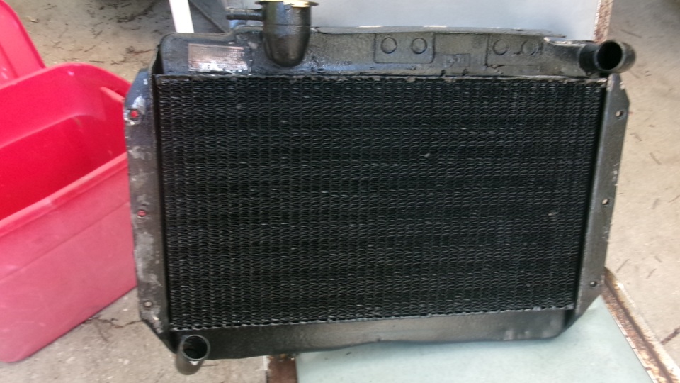
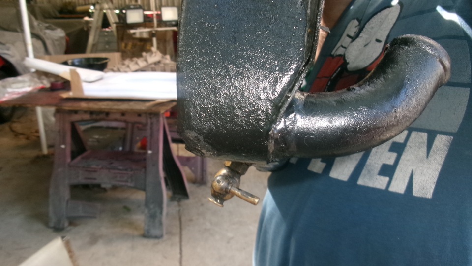
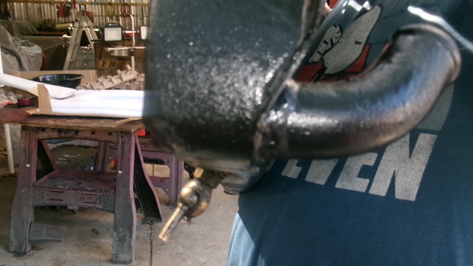
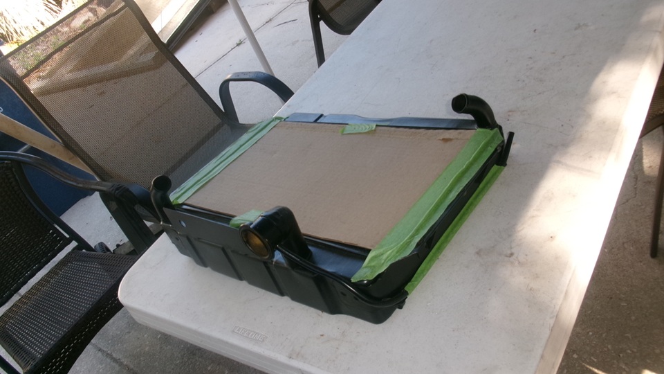
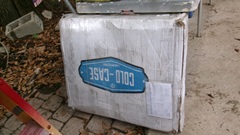
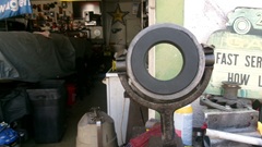
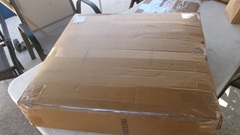
I was up way past midnight last night, but today would be a shorter work load, so we slept in until 9:30-am before breakfast , and start work after 10. Not long to assemble the electrical side of the engine, alternator, temperature sensor, distributor. Then we got to open the Christmas package, to get hands on the new cell core radiator. the box is by now a world traveler. I think it had an aluminum radiator delivered to a friend in California about five years ago. Then he shipped my 1986 vintage re-cored radiator to me in Florida some weeks ago. I shipped the leaky cell core radiator to Utah a few weeks back. And they shipped the newly re-cored cell core radiator back to Florida. And the box is not finished yet, more later. But there's the newly re-cored cell core radiator in ll its glory. This was very expensive, and 40 years late, so I want to celebrate and take lots of pictures for posterity. Not to mention,it is difficult to take good pictures of things that are painted black.

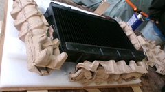
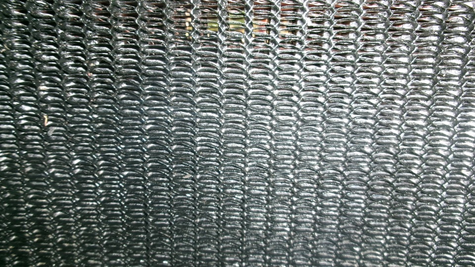
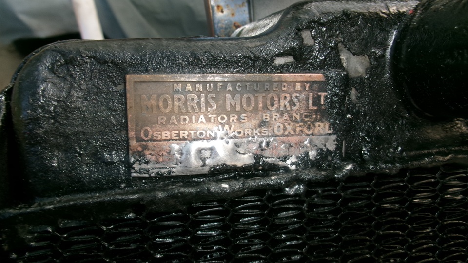
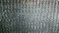
My first impression was, too much paint on the brass tanks and steel brackets, as they had painted over the original Morris Radiators tag, but the copper core was new with only the first coat of paint, so it will work fine, just as new. There is much information about the original cell core radiator construction and how it works in the Cooling Tech section of this web site.
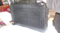
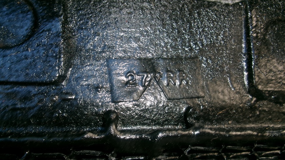
We spent some time with lacquer thinner and a very stiff bristle paint brush and rags cleaning paint off of the original tag.until we got down to some solder spatter that had obscured much of the original stamped part number. The "27TRR" tag is at center rear side of the top tank. That might have been from some prior shop work some time over the past 70 years.


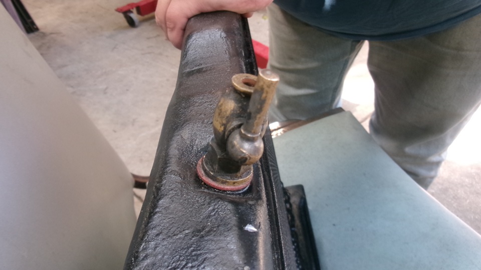
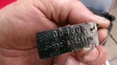
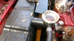
The loose2-line tag reading "00 1608 - J-MAC RADIATOR" on a thin piece of tag wire was attached at one of the mounting bolt holes, after painting and thread cleaning. Pretty sure that would be the job number of the tech shop in back that did the solder assembly work after Carnegie Industrial Radiator in S.L.C., Utah manufactured the cell core. A few minutes more spent fitting various fiber washers under the original factory drain cock to get it oriented where I might be able to work it with one finger while reaching down behind the radiator from above. That did work with the old re-cored radiator just removed.
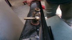

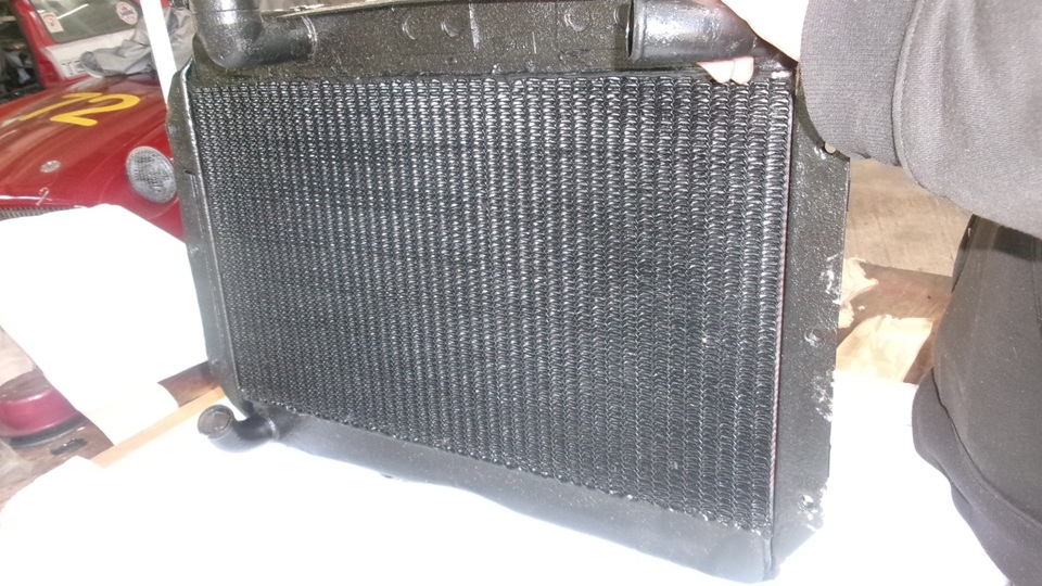
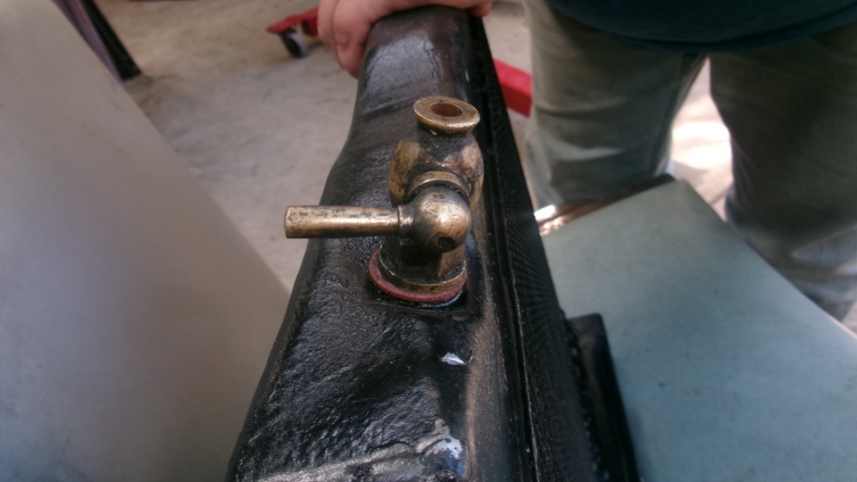
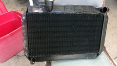
There it is upright, as installed in the car. Lever rotated to side is the open for drain position. Lever straight down is closed valve. Sweet to see the cooling system filled to the brim, pressure tight, no leaks. Notice the shallow (3/4-inch deep filler neck, as we requested, so it can accept a modern pressure cap with coolant recovery seals. Also the new hose barb, as requested, to accept the coolant recovery connection hose. No overflow pipe, no dribbling on the ground, and no need to remove the pressure cap to check coolant level.
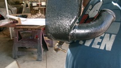
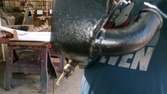
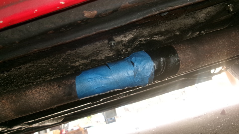
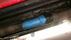
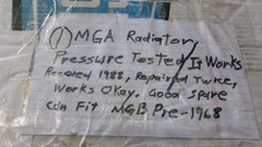
Then a few minutes to do something I've never done in my life, wrap a little exhaust bandage tape on the exhaust pipe center joint to stop a notable exhaust leak. This is a stainless steel exhaust system, 2008 last replacement . What , only 18 years? It came with 2-piece pipe for easy shipping, but the center clamp kept striking speed bumps. After a few years I removed the clamp and had a muffler shop weld the pipe joint. I suppose they used mild steel welding wire in a MIG welder, and the weld finally rested through. So now we get to field test the exhaust tape. Then we spent half an hour re-packing our old tube and fin re-core radiator from the late 80's, getting it clearly labeled, and put it in the storage attic at Tech Central for anyone who might have a future use for it. We have no idea where that box may be traveling next.

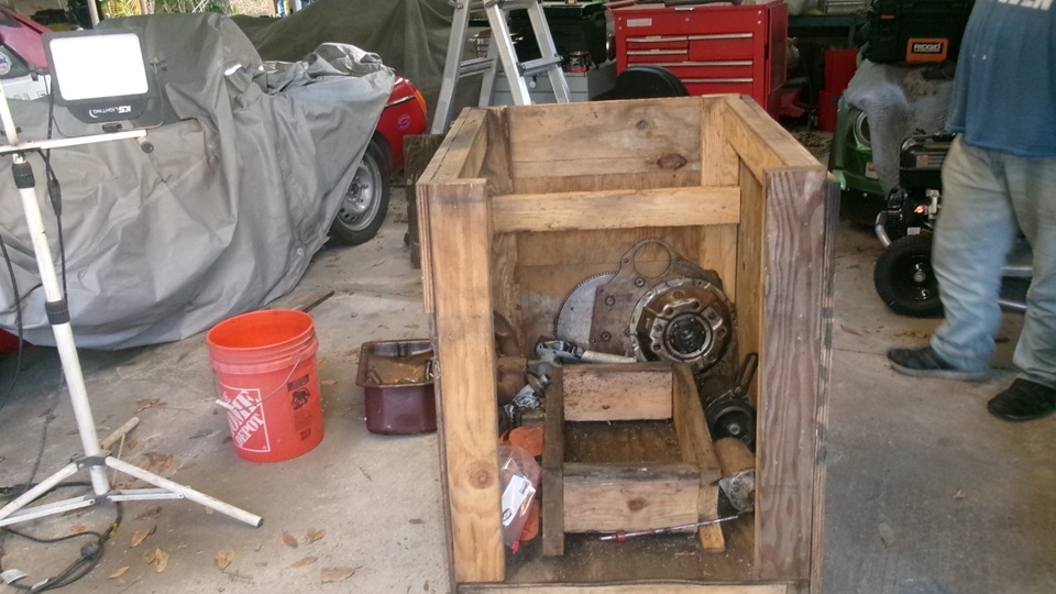
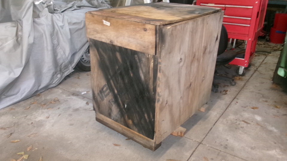
Last task for the day was to pick up the now historic faithful Magnette "loaner" engine, put the baby back to sleep in the cradle, and screw the covers on. Again no idea who may have a future use for it,but I certainly hope it's not us. This box is not going up the stairs to the attic, but it is on nice smooth caster wheels, so I suppose the guys will be using it for a mobile work table.


Friday, March20, 2026:
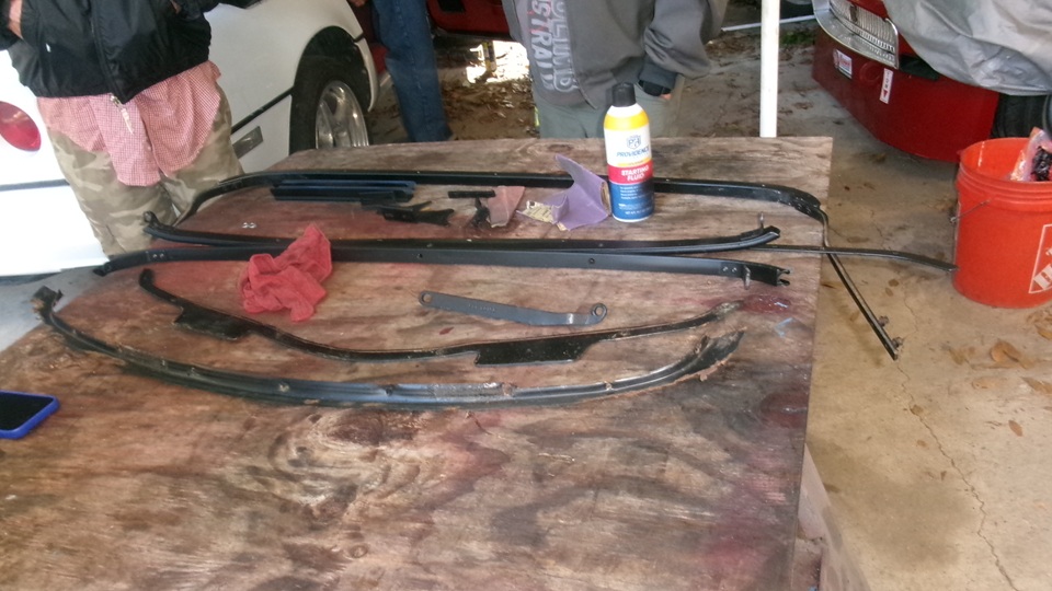
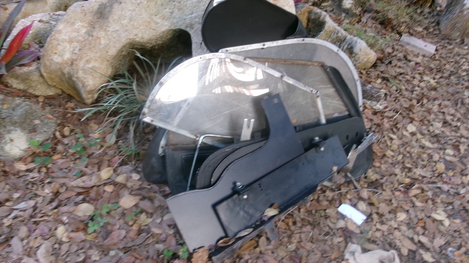
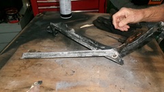
While the doctors at Tech Central are waiting for new patient today, they are fiddling a bit more with the Corvette convertible top parts. There was this significantly corroded rather heavy pot metal casting to connect the folding frame to the plastic body shell. Interesting to see how an American company may build a limited production car model.
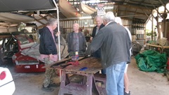

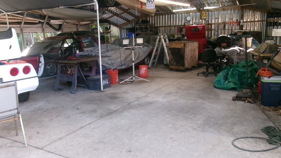
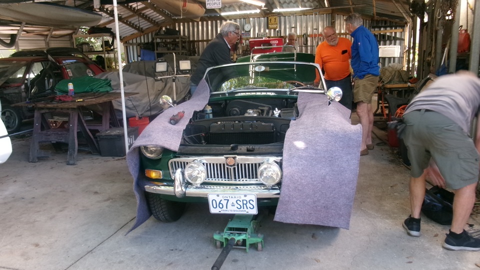
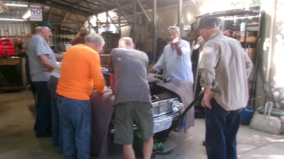
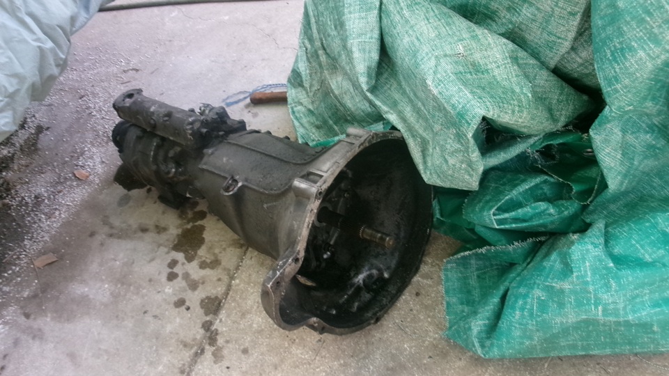
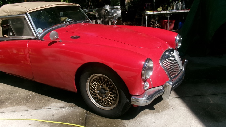
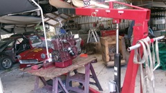
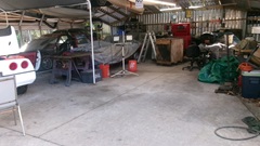
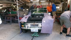
Clearing our some work space for the new arrival. This one is a 1967 MGB with original 18GB 5-main bearing engine, and a late model 4-speed 4-synchronizer overdrive gearbox, early inertia starter with later larger flywheel. That means they had to change the engine rear plate for the mating. It is a tight fit for the larger gearbox in the smaller tunnel space. It will be interesting to see how they get this power unit out for a needed clutch replacement.
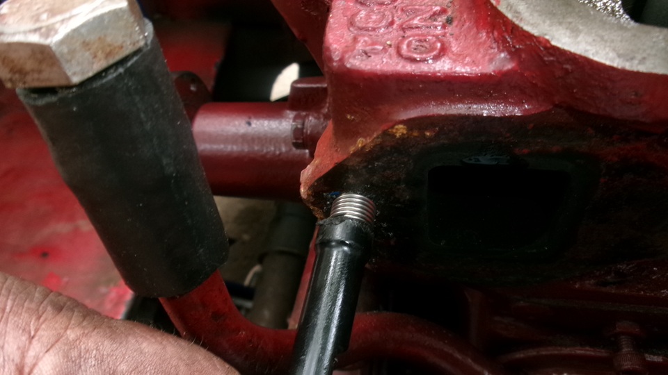
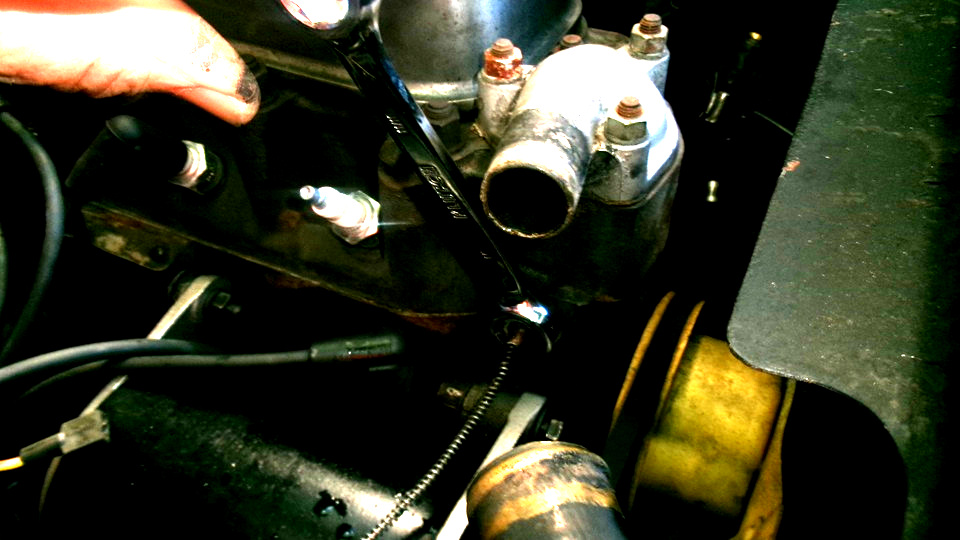
One serious problem was a temperature sensor flare nut stuck tightly in the cylinder head. You must use a 5-sided flare nut wrench here to avoid rounding off the corners of the thin wall tube nut. Even with the correct wrench it was tough going. Good to remove the thermostat cover for more motion clearance for the wrench.Then apply a longer wrench on end of the first one for more leverage. I tried a good push myself, and I swear they were applying more than 50 lb-ft torque. Apply a large Vise-Grip across the working end of the flare nut wrench to prevent it from expanding, and give it more torque. It will come loose, or something must break. Sure hoping it doesn't leave half a flare nut in the head with the seized thread. It was wrenching hard all the way out, and twisting the thin signal pipe for several turns, as the sensor bulb was firmly stuck in the ntube nut. It did finally come out, but we will need to check later if the fluid pipe was damaged (very likely), in which case it will need to be repaired (a fun little chore itself).
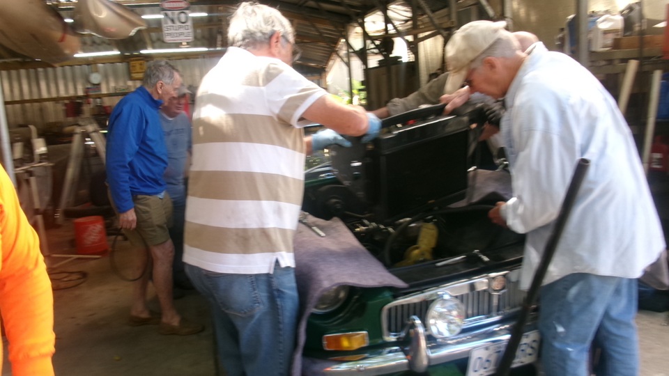
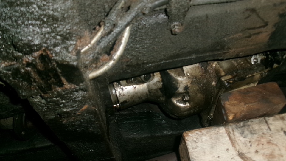
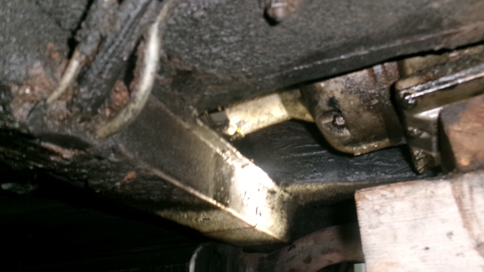
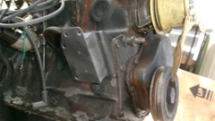
Must remove the generatortor get to the RH engine mount bolts. They thought they might get to the LH engine mount bolts (maybe), and wanted ro remove the engine with manifolds and carburetors still attached, but I'm pretty sure the exhaust manifold will not get past the steering column. No one wnted to lay unbderneath to remove six nuts from the exhaust down pipe flanges, so they conceded to remove the carburetors and detach the exhaust manifold from the head while leaving it attached to the pipes. They did manage to detach the ratiator mount panel from the body and pull it out with the radiator still attached.


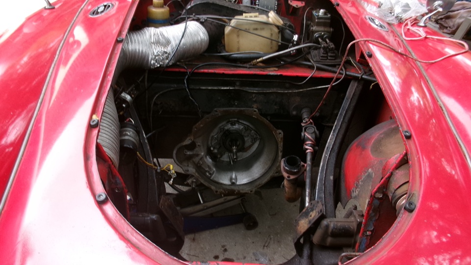
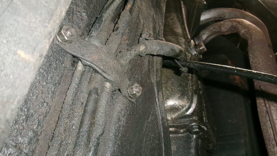
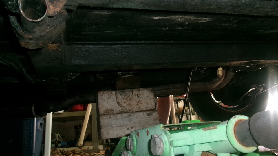
Meanwhile a few people underneath (including myself) working to detach the propshaft front flange from the gearbox, and unbolt the rear mount crossmember from both gear box and frame. Then work a trolly jack to lift the tail flange above the remaining tunnel lower brace, without removing that piece, while pulling the whole lump forward.

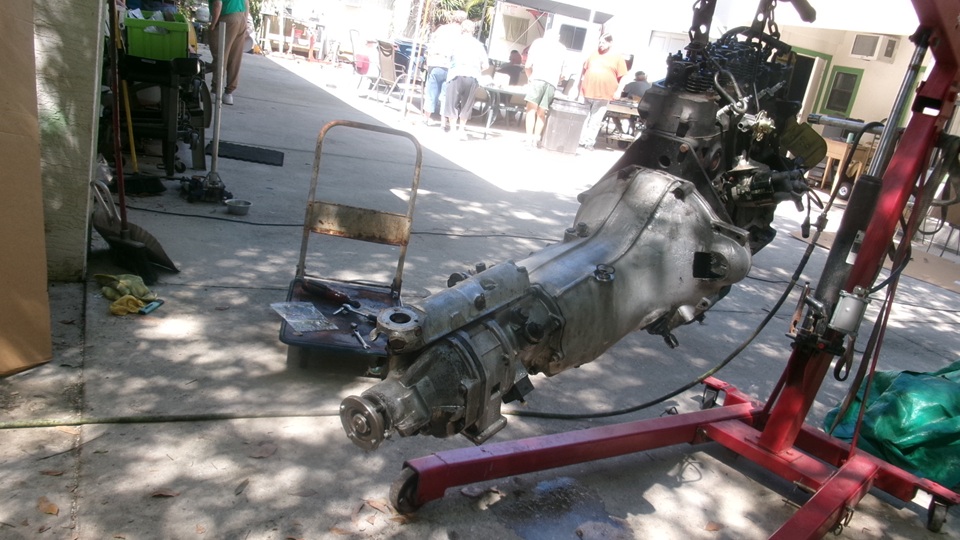
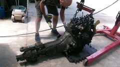
Ready to lift, muscle the exhaust manifold away from the cyinder head. No way the hanging oil filter is going past the engine mountpedestal, so they finally concede to remove the filter canister while the engine is hanging on the lift. PLEASE detach the speedometer cable from the hgearbox so you don't destroy the cable. No? They insist on pulling the lump forward, wanting easier access to the cable rear end, so naturally the cble gets multiple kinks and will likely neeed tto be replaced. It didn't help that whomever installed the overdrive gerbox had removed the smalln right angle cable drive gearbox, so we need to think about procuring one of those before it goes back togther.


I was shephearding the trolly jack the wood blocks to keep the gearbox at good height to assure the rear flange could pass forward over the tunnel lower brace that they didn't want to remove (while smashing the speedometer cable). That was a pain in the back.


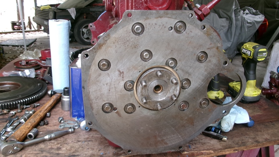
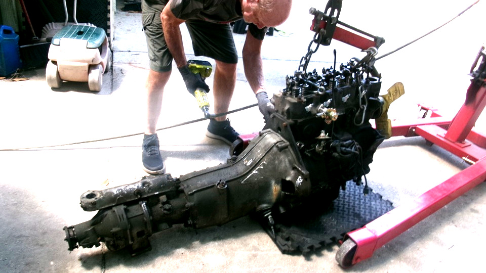
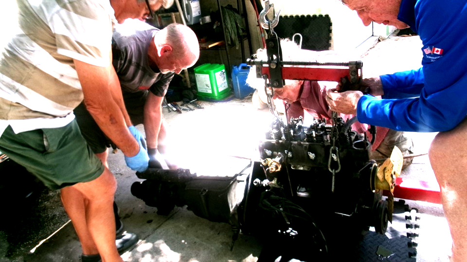
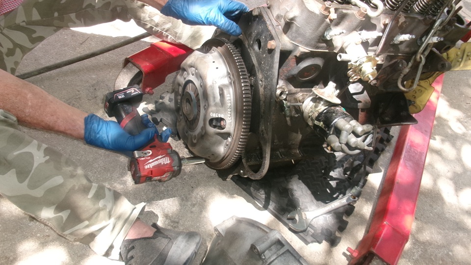
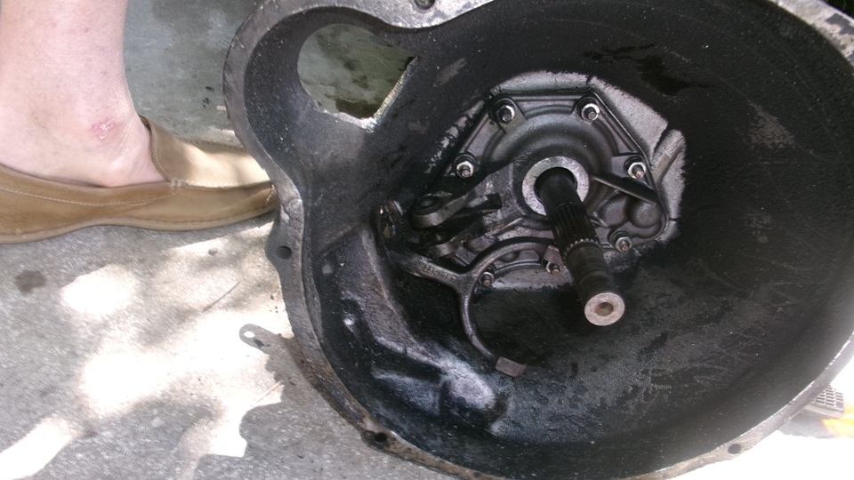
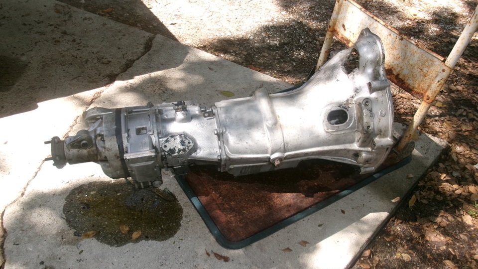
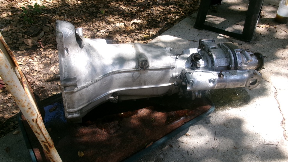
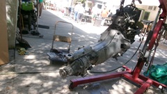
Finally the lump was lifted out, engine and gearbox together. Set it on the floor and get after the bellhousing bolts to separate gearbox from engine.
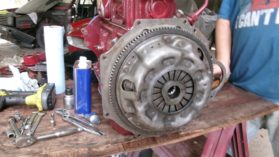
Quick work to remove the pressure plate and friction disc. Oddly, it struck me that the friction disc was not half worn, and it should not have been slipping under power, but it was. That makes me suspect the clutch slave hydraulic hose may have been partially clogged, interfering with clutch re-engagement. Or maybe the slave cylinder was one of the defective ones from several years ago when they had an aluminum piston that would totally wear out in very short mileage to cause terminal leaking and/or sticking. Well, the slave cylinder issue has been resolved many years ago, except there may be a few faulty ones still in inventory somewhere, and we now have in hand a new slave cylinder "kit" with new hose and all the proper fittings to go with it. And we are ordering a new release arm pivot bolt and bushing and rubber dust boot.
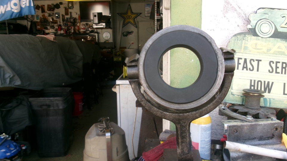
However, .... there is another SERIOUS problem that I spotted the instant I saw the new clutch release bearing come out of the new clutch kit. The carbon relese bearing is a Faulty Replacement Part that cannot be installed into the original clutch release arm, because the bearing iron shell is machined a bit too wide at the shoulders for the pivot pins. It can be assembled with only one retaining clip, but the second clip wlil not fit. The supplier's solution for this was to add to the release bering package a second set of spring wire retaining clips (originally intended for use with other cars like MGTD, MGA, early MG Midgets), and drill the ends of the MGB release bearing to accept the incorrect wire clips (please delete the spring steel clips). The remaining problem then is, the MGB release arm does not have the required detent dimples in back to retain the MGA wire clips., If it was assembled that way, it is guaranteed the wire clips would fall out in short order as soon as the car will be driven. Also a few years ago there was already a five year history of this part failing when the crbon thrust puck would break up or fall out of the retainer. Then you get to pull the engine out again to do it all over again, and no one knows how much more collateral damage when it falls apart. This is exactly wht bit me in the ass three years ago, so I have a right to be pissed off and ranting about this issue again.

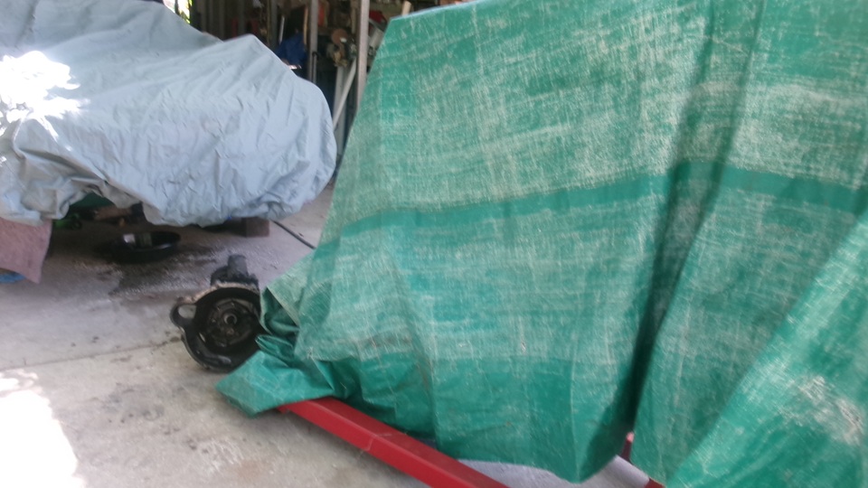
The expedient fix is to grind about 0.010-inch off at both inside surfaces of the release arm cradle ears, so the abnormal release bearing can be installed with original spring steel clips. That means bastardizing a perfectlygood original part to accommodate using a known Faulty Replacement Part. This all very bad practice. We will continue to consider this over the week end. Cover the car and engine to be out of the weather. The gearbox is likely to pressure washed come Monday, about the time new parts will be ordered and shipped.

Saturday, March21, 2026:

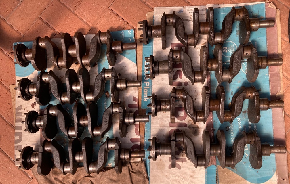
Made a new Engine Tech page CS-110A for Australian produced MGA crankshafts with at least five different casting numbers. This should keep people busy for a while trying to figure out what they were made for, and maybe if they were castings or forgings. -- Much of the rest of the day spent processing photos and notes from yesterday's tech session. -- Late night phone call with the guy who owns the MGB with engine out, reviewing a few issues, making plans for parts, repairs and reassembly.
Sunday, March22, 2026:
Update to the new tech page on Australian crankshafts, now that we know what they are. -- Update address links for Universal CarnegieManufacturing, after their move from PA to UT in 2024. This is the shop that can rebuild your original MGA cell core radiator.
Monday, March23, 2026:
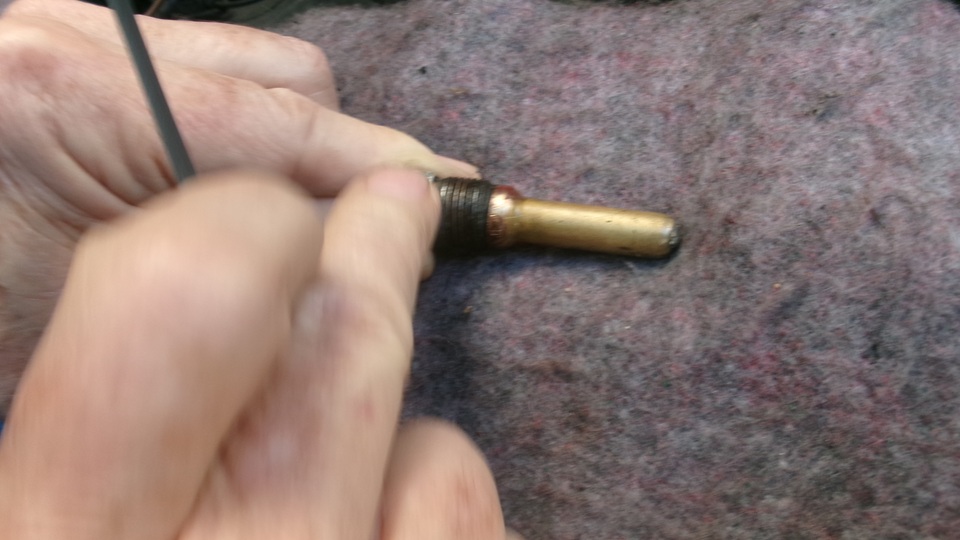
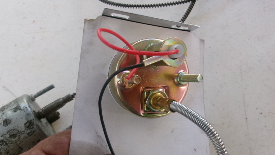
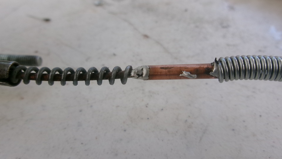
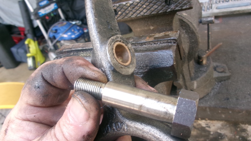
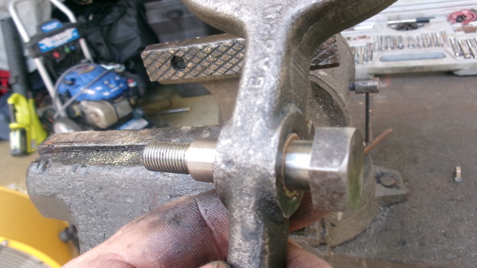
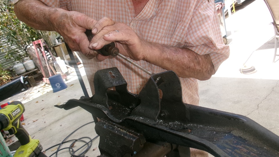
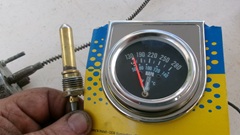
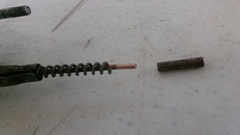
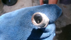
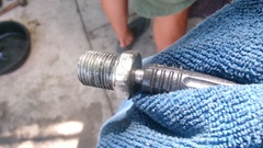
Back to Tech Central with Bruce Mitchell, the guy who owns the MGB with engine currently out. Cleaning up a few details left over from Friday, the first item was the analog temperature sensor bulb that was rather harshly removed from the cylinder head. When the sensor was stuck in the flare nut, they had twisted the thin fluid pipe several turns as it was being unscrewed. We stuck the sensor in a cup of boiling water to verify that the temperature gauge would still work, and I was pleasantly surprised that it did. We spent some time with a flare nut wrench, small Vice-Grip, pocket knife, screwdriver and penetrating oil to get the flare nut turning free from the tube and spring wire and metal ferrule inside. A little more time with a small file taking burrs off of the nut to assure the flare nut wrench could work to reassemble it later. Then a comparison of the original flare nut (top) and new flare nut (bottom) showing the flare nut on a modern replacement gauge is shorter than original nut.

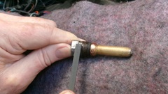
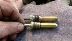
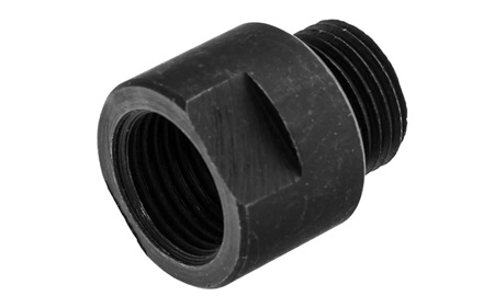
If you would use one of the modern parts in your car, you would need the long to short thread adapter to screw into the cylinder head before installing the new sensor bulb, BMC part number 11K2846, or Moss Motors USA part number 361-065. If you want to replace the flare nut, you have to break the thin pipe, replace the nut, and solder the pipe back together without losing the volatile ether fluid from inside the bulb. I have never done this with a working gauge, but I have repaired a few that had a broken pipe. The "cheap trick" there is to start with a new cheap analog temperature gauge, place the thermal bulb in brine ice water to keep the ether as liquid (prevent boiling), and then cut and solder splice the new pipe onto the old gauge.


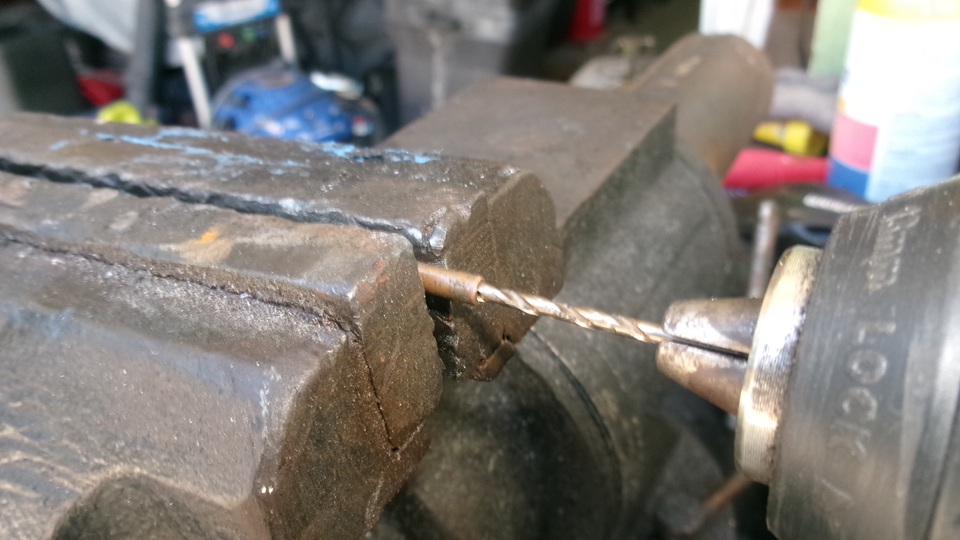
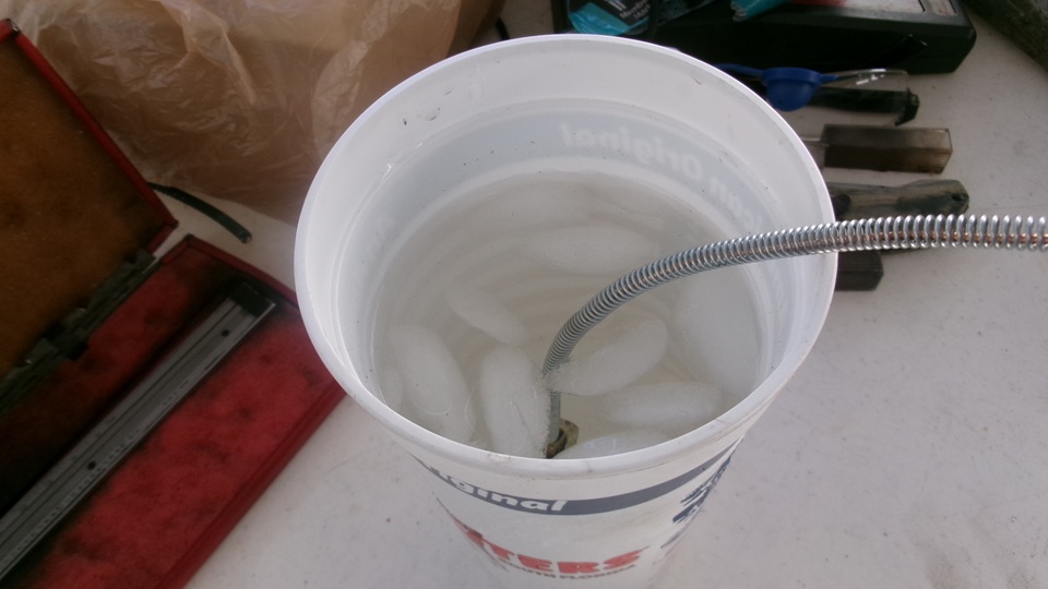
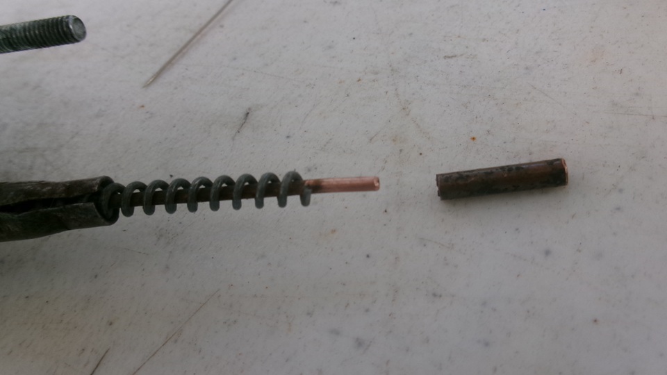
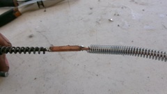
We actually had the materials on hand to do this, as well as a gauge needing repair, so we gave it a shot (again). Needing a tubing splice, start with a half inch of copper tubing with 1/16" ID, 1/8" OD. Drill half way through from each end (if needed) to give a few thousandths of an inch clearance for the solder joint. Place the thermal bulb of the mew gauge in ice water with a saturation dose of salt added to reduce the freeze temperature (to keep the volatile fluid from boiling).


Cut the tube on the old gauge a couple inches behind the gauge, cutting the guard wire farther back to expose at least 1/4-inch of bare tube. Poke a straight pin into the cut tube end to assure it clear. Clean the tube and tin it with solder, to be sure the solder sticks before going on, assuring you do not solder over the end of the tube. Then solder the short splice tube onto the stub end of the old gauge, and use the pin again to assure the small tube remains clear. Cut the tube of the new gauge behind the gauge, again leaving the tube end exposed beyond the spiral guard wire. Tin the end of the new tube, and solder it into the sleeve coupling. The solder joints to require a clean joint and hermetic seal, so no cold solder joint is allowed. Then you can move the new thermal bulb from the ice water into a cup of boiling water. If you immediately smell ether and the gauge does not work, you lose and get to start over. If the repaired gauge works, you win, and save yourself some money on the repair cost. You may be able to twist and move the new guard wire coil over the splice joint. Otherwise, place a piece of stiff wire along side and tape it up securely to serve as strain relief.

We did a little pressure washing on the MGB gearbox so it won't be so slimy next time we handle it. Also pressure washing the MGA wheels and giving the car a rare bath and resetting tire pressure all around, including the spare tire and trailer tires.


Tuesday, March24, 2026:
Catching up yesterday's photos and notes. Working on a new tech page with more information on sticking MGA bonnet latch, as it seems to be a common problem, and often perplexing.
Wednesday, March25, 2026:
Finished a new tech page for Stuck Bonnet Latch with color diagrams and notes on how it works and how to get it unstuck.
Someone wanted an update on the 1800 engine with new crankshaft. Not going anywhere yet, so we have driven it no more than 50 miles in 5 days, but it does cold start and short trips 1 to 5 miles at least twice a day, and so far it seems perfect, no reason to think otherwise. Still need to get it out on the expressway for a higher speed distance run.
Broke the RH wing mirror while trying to adjust it before 8-am. Redialing calls all day until I got an answer and could order a new RH wing mirror after 7-pm. Not a total lost day, but it took a couple hours of redialing through the day. New mirror is on its way.
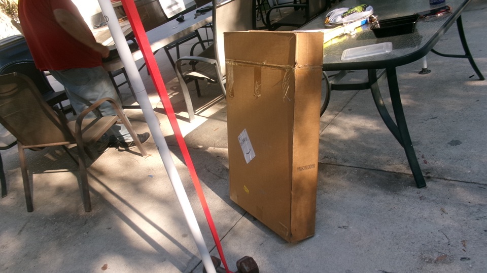
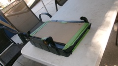
Finally got the decision on the faulty new MGA radiator we bought in mid January. Now time to box it up for measurement and weighing to get a shipping label to send it back to Moss Motors warehouse in Petersburg, VA. That's not where it originally came from, but they were the primary source in the supply chain, so they will now take it back. Not urgent, so we may put that off until Friday.
Thursday, March26, 2026:
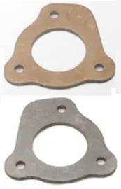
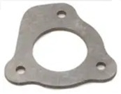 Started on some new Part Numbers tech pages for the camshaft timing chain drive assembly parts. First one up is the 11G136 camshaft locating plate with early and late style, three different part numbers plus gasket and fasteners.
Friday, March27, 2026:
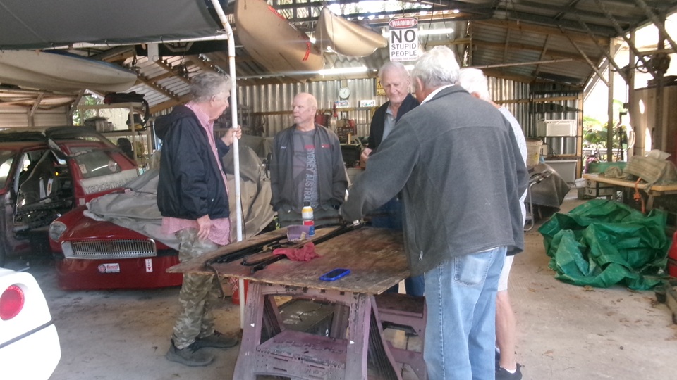
Morning at Tech Central with at least half a dozen members already on hand. There's our first replacement 18G crankshaft that didn't work out, waiting for the scrap metals man pickup. A new pile of old side curtain parts for who know what, also discarded for metals collection I suppose.

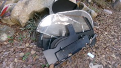
Now clear to return the $400 new MGA radiator that didn't fit in the car, we need to get that packaged up, measured and weighed for shipping. we were lucky to find a box of appropriate size, so not long to finish the packaging with padding. cut, fold, tape, measured and weighed. 8x23x25-inches, just shy of 17 pounds. Later in the evening we will get that called in for a Return Authorization number and shipping label. The trick here is that we bought it from Scarborough Faire, but they got it from Moss Motors. Now it will be returned directly to Moss to avoid redundant serial shipping. Tough nut that Moss is now requiring pre-authorization with an R/A number before returning anything. Customer service be damned.
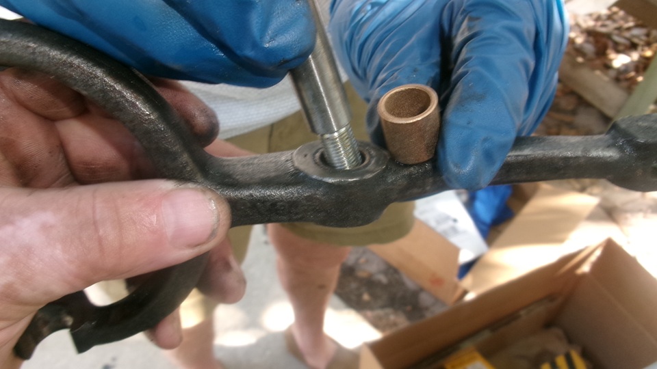
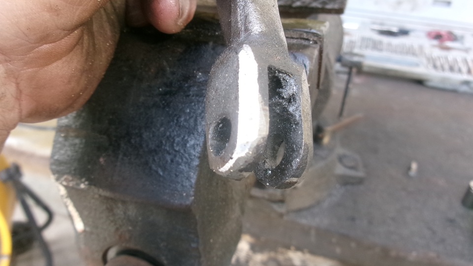
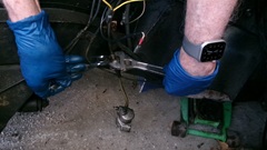
Getting back to the MGB clutch transplant, fitting clutch release parts to front of the gearbox before mating to engine. Install a new bushing in the release arm.


Grind corners on the clevis end of the release arm to allow easier installation of the rubber dust excluder boot. Relieve the inboard surfaces of the release arm fork slightly to accept the (faulty) oversize replacement release bearing. Install the arm with new pivot bolt, attach the release bearing, and install the rubber boot. One heavy flat washer and one lock nut to go.


Installing new clutch hydraulic hose and salve cylinder. The hose being removed turned out to have a swivel fitting on the input end where the steel pipe connects. I had never seen this type fitting on a clutch hose, but it worked okay and was not plugged. More significant was that the old hose was small bore like a brake pipe, where a clutch hose should have larger bore for fast return when the clutch pedal is released.The new replacement hose is more traditional type with larger bore.
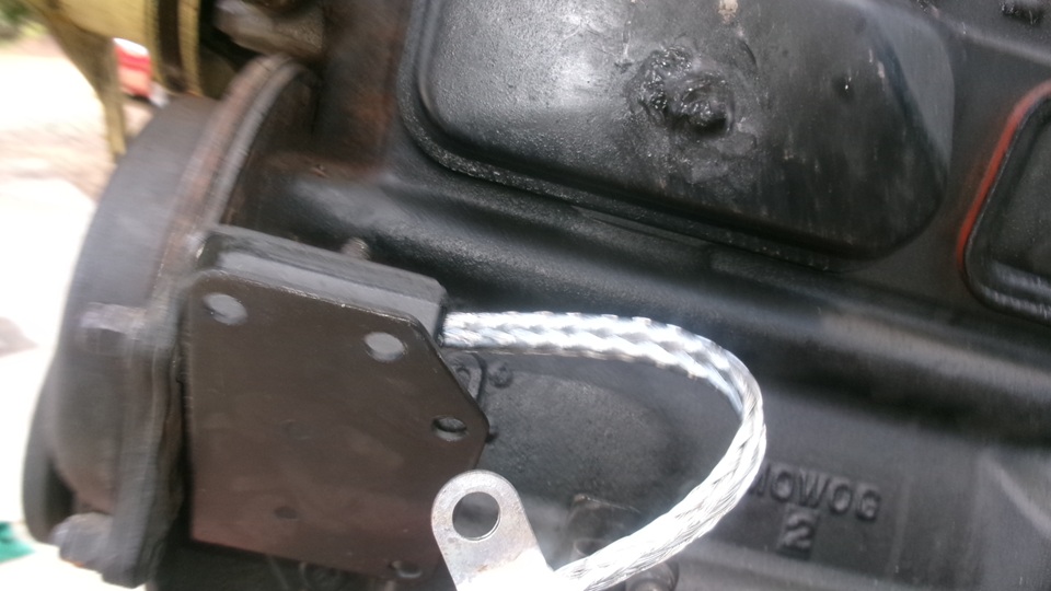
Meanwhile, the guys had the gearbox bolted up to the engine, and new engine mounts installed.

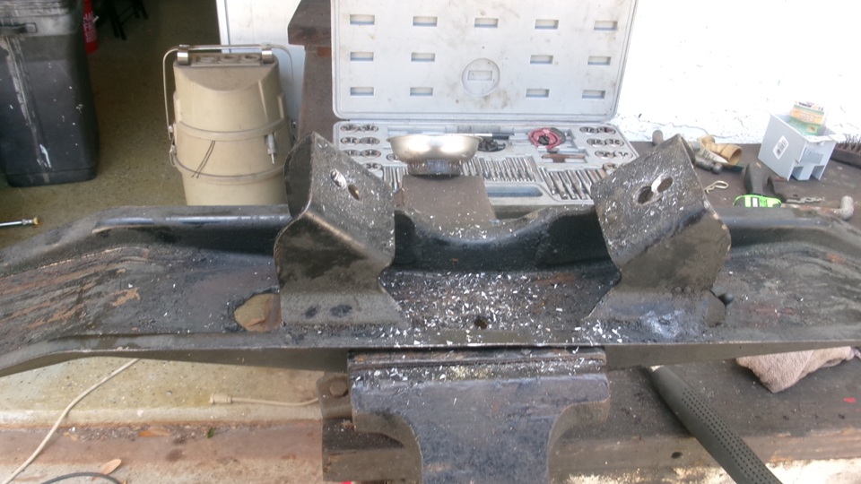
Jerry was busy modifying the gearbox rear mount cross member. Drill a couple of holes, and grind out slots between the holes, to make it possible to drop the gearbox straight down while clearing the rubber mount suds.

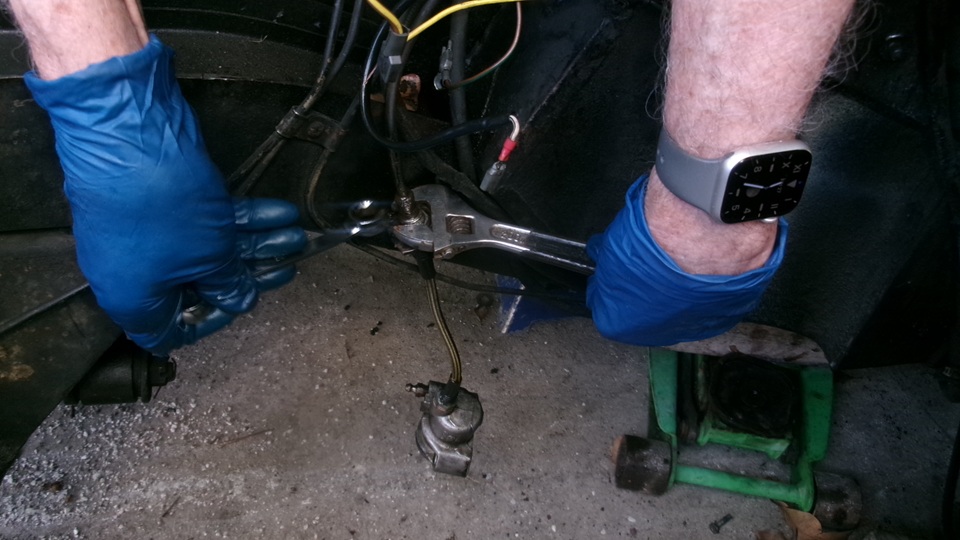
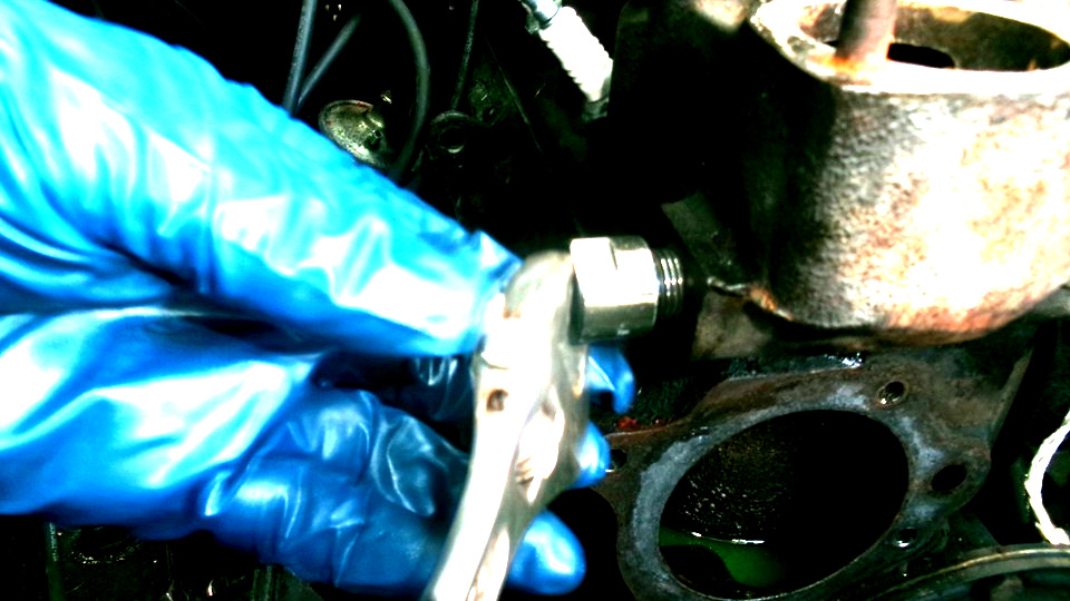
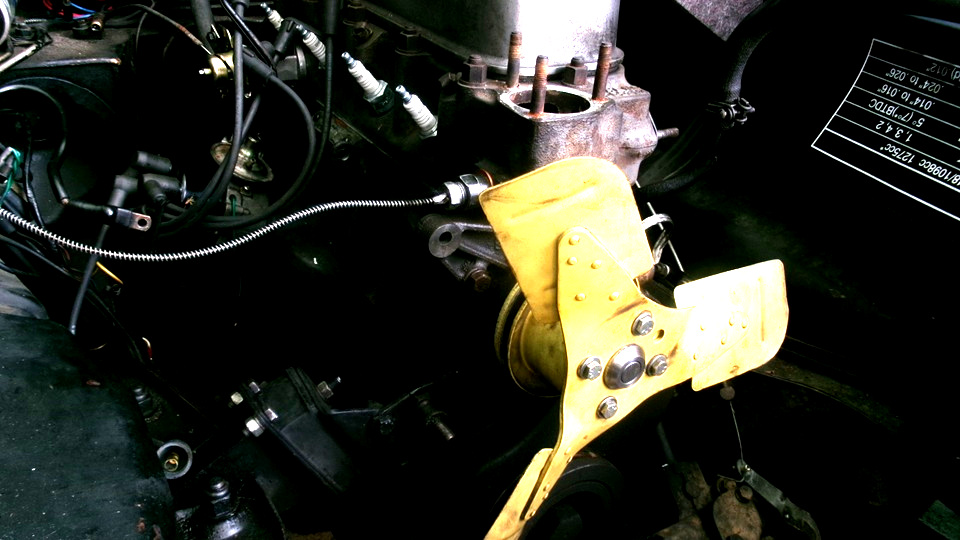
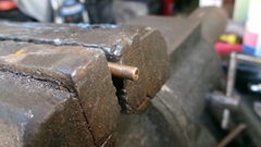
Finally the engine and gearbox were in, bolted down on on the gearbox rear mount and engine mounts. We took time to remove the water pump for access to clean up threads on the temperature sensor and install an adapter fitting with a copper seal washer, very tight. Thus allows easier R&R of the sensor as well as allowing use of a more modern sensor with shorter threads on the flare nut. Then reinstall the water pump and thermostat and water neck with new gaskets, and that was a good place to stop for the day. The guys will be back next week.

Saturday, March28, 2026:
Catching up photos and notes, encountering a reoccurring problem with Firefox web browser. I bought a new computer two years ago, and all was well for a while. Then there was an update in the browser program that disabled an important function. When my web page opens a picture image in a new or separate browser window (which I do lot), you should be able to click on multiple pictures in series, and then use the "Back" and "Forward" buttons to play back the pictures like a slide show, but that's what quit working some time ago, and now I am PO'd enough to take time to figure out how to fix it. The expedient solution was to back up and reload an older version of the browser. One year back was not far enough, but an 18 month old browser version has it working again. That killed half a day by the time it was configured for full functionality again. I got my bookmarks back, but haven't restored my updated dictionary file. This ain't over yet. I hate software designers, and the companies that let the designers get way with crap like that.
Sunday, March29, 2026:
Half the morning chasing more browser problems. Managed to retrieve my Personal Dictionary data file (persdict.dat), so all my special spelling words (like "gudgeon" pin) can be recognized by a spell checker. Need to keep the 18-month old browser version active so the" slide show" Back and Forward buttons can work in a target window.
 Now trying to defeat the automatic pop-up that is pushing a browser update every time I open a new browser window (grrrrrr).
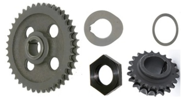
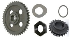
Meanwhile, just uploaded six new Part Numbers tech pages for more parts of the camshaft timing chain drive assembly:
1A2028 Gear -crankshaft (sprocket) --
2K6633 Washer -packing (for crank gear) --
1G2340 Gear -camshaft (sprocket) --
11G203 Gear -camshaft (sprocket), --
2A759 Washer -locktab (for cam gear nut) --
6K629 Nut-for camshaft gear.
Monday, March30, 2026:
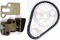
Time to kill, so more Part Numbers tech pages for timing chain and chain tensioner parts:
2H4905 Timing Chain -
17H343 Chain tensioner servicing kit -
17H6680 Chain tensioner -
17H31 Slipper head -
17H6679 Allen key (service tool) -
AEC339 Joint (gasket) -
AEC340 Washer -locking (locktab for mounting screws) -
1B3363 Washer -locking (locktab for hex head plug) -
Zoom Tech Session with John Twist in the evening, chatting about Tubes, Hoses, Pipes and Cables used in MG cars.
Tuesday, March31, 2026:
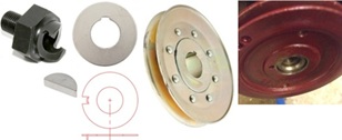
Posting several more Part Numbers tech pages for:
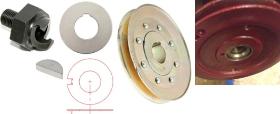
1H765 Starting dog nut, -
1G1319 Locktab for dog nut -
AEH429 Locktab for dog nut, Twin Cam -
2H326 Key for crankshaft gear and pulley -
11G81 Crankshaft pulley for pushrod engine -
AEH428 Crankshaft pulley for Twin Cam engine -
AEH427 Oil thrower for Twin Cam engine
|